Calibration method, communication system, frequency control method, and communication device

A technology of communication device and calibration method, which is applied in transmission system, wireless communication, baseband system, etc., can solve problems such as non-existence and may not be able to guarantee calibration accuracy, and achieve the effect of simplification

Inactive Publication Date: 2010-03-24
MITSUBISHI ELECTRIC CORP
View PDF1 Cites 87 Cited by
  • Summary
  • Abstract
  • Description
  • Claims
  • Application Information

AI Technical Summary

Problems solved by technology

In addition, there is the following problem: Since whether the distance between antennas can be directly converted into a phase difference depends on the surrounding environment, the calibration accuracy may not be guaranteed especially in a multipath environment
Also, in the technique described in Non-Patent Document 1, calibration is also performed between adjacent antennas, but there is a problem that as the number of antennas increases, it is necessary to repeatedly transmit and receive more signals for calibration.
In order to realize such new wireless transmission, a method that can control the relative carrier phase of multiple signals in the receiver is needed, but no such method currently exists
[0021] In addition, when a plurality of transmitters perform signal transmission simultaneously by setting so that the carrier phase becomes the same in the receiver, it is important to perform appropriate signal transmission and transmission power control in each transmitter, but not Such technology exists

Method used


Image

  • Calibration method, communication system, frequency control method, and communication device
  • Calibration method, communication system, frequency control method, and communication device
  • Calibration method, communication system, frequency control method, and communication device

Examples


Embodiment approach 1

[0175] In this embodiment, a calibration plan for correcting a signal in the TDD method so as to establish the reversibility of the transmission path measured by the digital unit will be described.

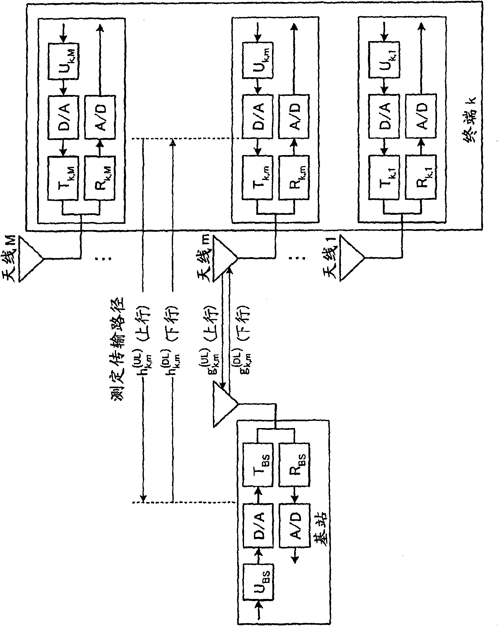
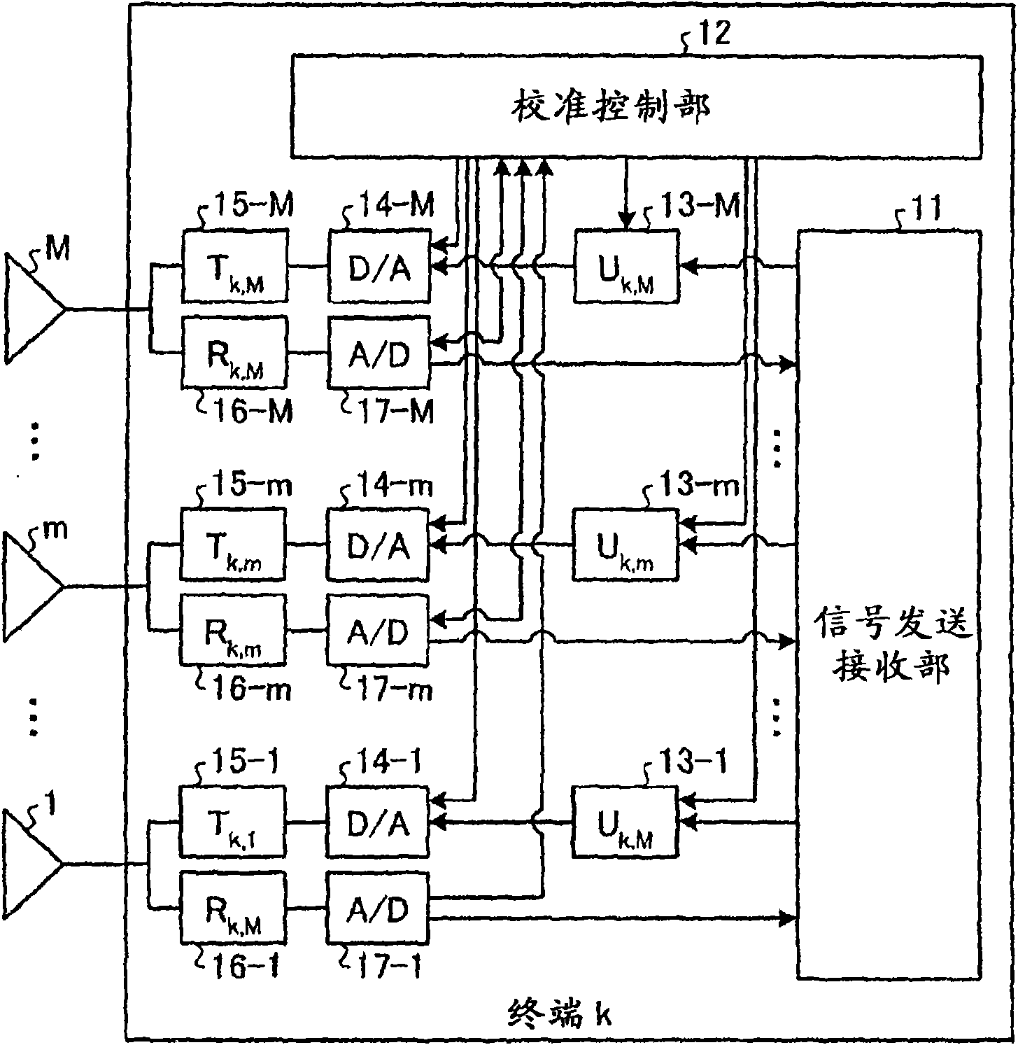
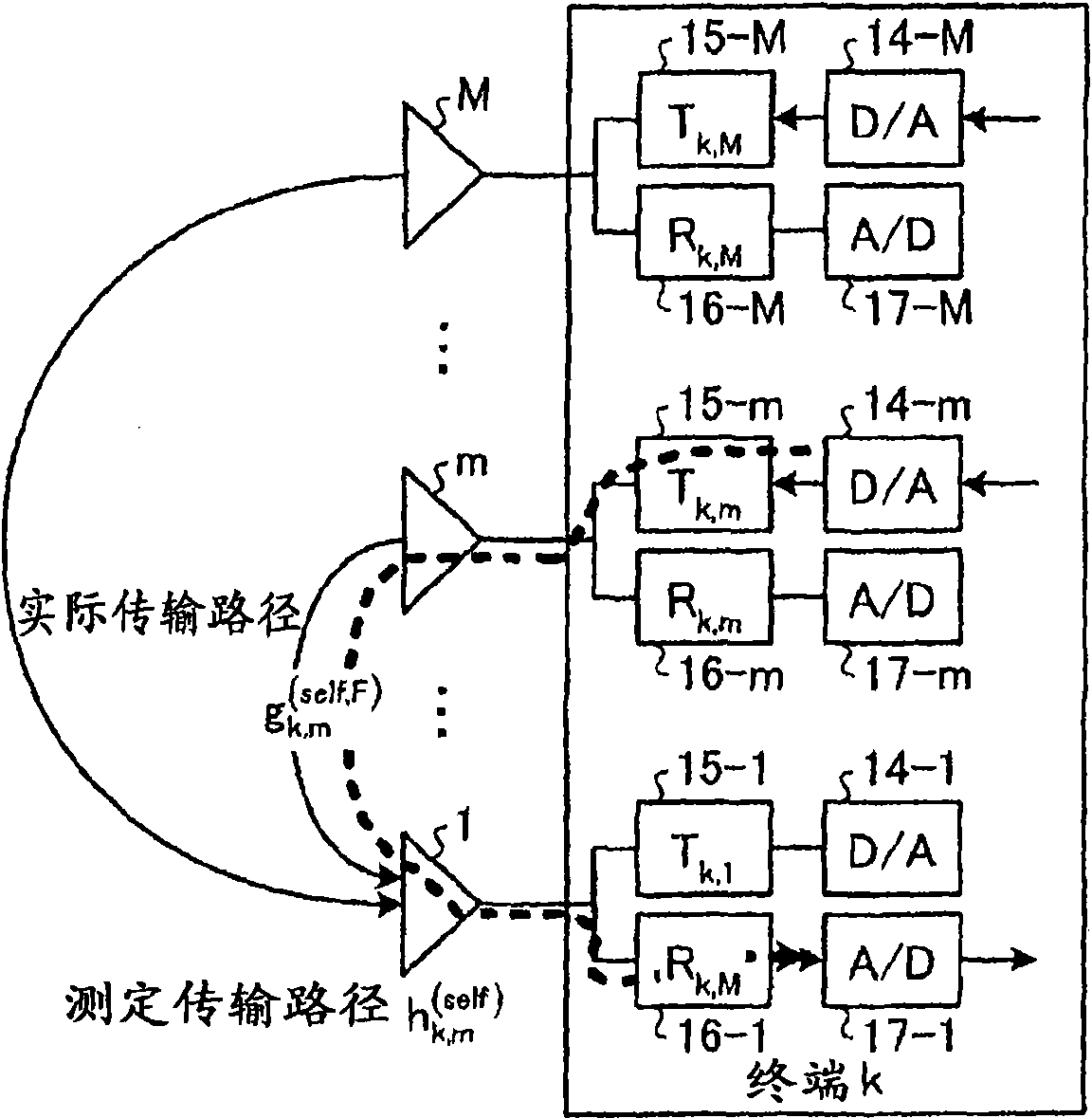
[0176] here, figure 2 It is a diagram showing a configuration example of a terminal device that performs calibration between a plurality of antennas. In addition, FIG. 3 is a diagram showing a signal transmission model when calibration is performed between a plurality of antennas of a terminal, Figure 4 It is a flowchart showing an example of the calibration procedure in the first embodiment.

[0177] figure 2 The shown terminal k has: a plurality of antennas m (m=1, ..., M); a signal transmission and reception unit 11; a calibration control unit 12 for controlling the calibration method of the present invention; A plurality of signal correction units (u k,m ) 13-m (m=1, . The output signal of the D / A converter 14-m is multiplied by a plurality of transmission signal ampli...

Embodiment approach 2

[0206] Next, Embodiment 2 will be described. In this embodiment, the setting of the transmission power of the pilot signal used for channel measurement will be described.

[0207] For steps (1-1) to (1-4) described in Embodiment 1, namely Figure 4 To achieve high calibration accuracy in the processing of steps S41 to S44 shown, it is necessary to obtain stable channel measurement accuracy. Therefore, in this embodiment, a scheme will be described in which the channel estimation accuracy is stabilized by changing the transmission power of the pilot signal for channel measurement depending on the antenna. In addition, a configuration example of a terminal device performing calibration is the same as that of Embodiment 1 (see figure 2 ).

[0208] Such as Figure 5 As shown, for example, when antennas 1 to 3 are considered, the transmission gain between antennas 1 and 3 (h k,3 self,F or h k,3 self,R ) is less than the gain between antennas 1 and 2 (h k,2 self,F or h k,2...

Embodiment approach 3

[0218] Next, Embodiment 3A will be described. In the calibration procedure of the first embodiment described above, the phase and the amplitude are corrected at the same time, but in this embodiment, the calibration procedure when only the phase is corrected will be described.

[0219] Although the simulated characteristics T of each antenna in reality k,m , R k,m It varies depending on the temperature, but generally the amplitude characteristics of each antenna are similar. On the other hand, the phase characteristic fluctuates greatly, which affects communication quality. Therefore, correction of phase characteristics becomes particularly important in calibration. In addition, the correction of only the phase can be realized only by the phase shifter, so the hardware is further simplified.

[0220] Therefore, in this embodiment, a self-calibration procedure in which only phase correction is performed by the control described below will be described. In addition, a confi...


PUM


Abstract

A calibration method comprising a first channel estimation step in which a pilot signal is transmitted from a first antenna and it is received by a second antenna that is different from the first antenna to calculate a first channel estimation value; a second channel estimation step in which the pilot signal is transmitted from the second antenna and the pilot signal is received by the first antenna to calculate a second channel estimation value; and a correction coefficient calculation step in which a correction coefficient is calculated by using the first and the second channel estimation values.

Description

technical field [0001] The present invention relates to digital processing for smooth signal transmission and reception in wireless communication. Background technique [0002] Demand for high-speed wireless communication is increasing, and high-speed wireless communication transmission technology is required. Therefore, recently, a technique in which a transceiver performs high-speed signal transmission using a plurality of antennas has been extensively studied. An environment in which a base station simultaneously performs spatial multiplexing transmission to a plurality of terminals using a transmission beam in future mobile communications is also envisioned. In addition, it is also possible to reduce the transmission power required for communication when performing appropriate transmission beamforming in the terminal. Therefore, high-precision transmission beamforming technology will become an important issue in the future. [0003] Among them, when transmitting beamf...

Claims


Application Information

Patent Timeline
Patent Type & Authority Applications(China)
IPC IPC(8): H04B17/00H04J99/00
CPCH04L27/2647H04B17/0062H04L25/0224H04W52/241H04W52/325H04B17/12
Inventor 原嘉孝平明德田岛贤一纪平一成高野道明石冈和明能田康义
Owner MITSUBISHI ELECTRIC CORP
Why Eureka
Try Eureka