Pneumatic rubber cutting device

A rubber and cutting technology, which is applied in transportation and packaging, metal processing, winding strips, etc., can solve the problems of poor flexibility, high energy consumption, and poor cutting length accuracy, so as to improve production efficiency and high cutting accuracy , the effect of reducing energy consumption

Inactive Publication Date: 2010-03-31
LUOHE LOUFOR STATIONERY MFG
View PDF0 Cites 56 Cited by
  • Summary
  • Abstract
  • Description
  • Claims
  • Application Information

AI Technical Summary

Problems solved by technology

[0003] The purpose of the present invention is to overcome the shortcomings of poor cutting length precision of the current mechanical transmission rubber cutting mechanism, high energy consumption and poor flexibility when cutting thinner and shorter rubber products, and provide a new type of pneumatic rubber cutting machine

Method used


Image

  • Pneumatic rubber cutting device
  • Pneumatic rubber cutting device
  • Pneumatic rubber cutting device

Examples


Embodiment 1

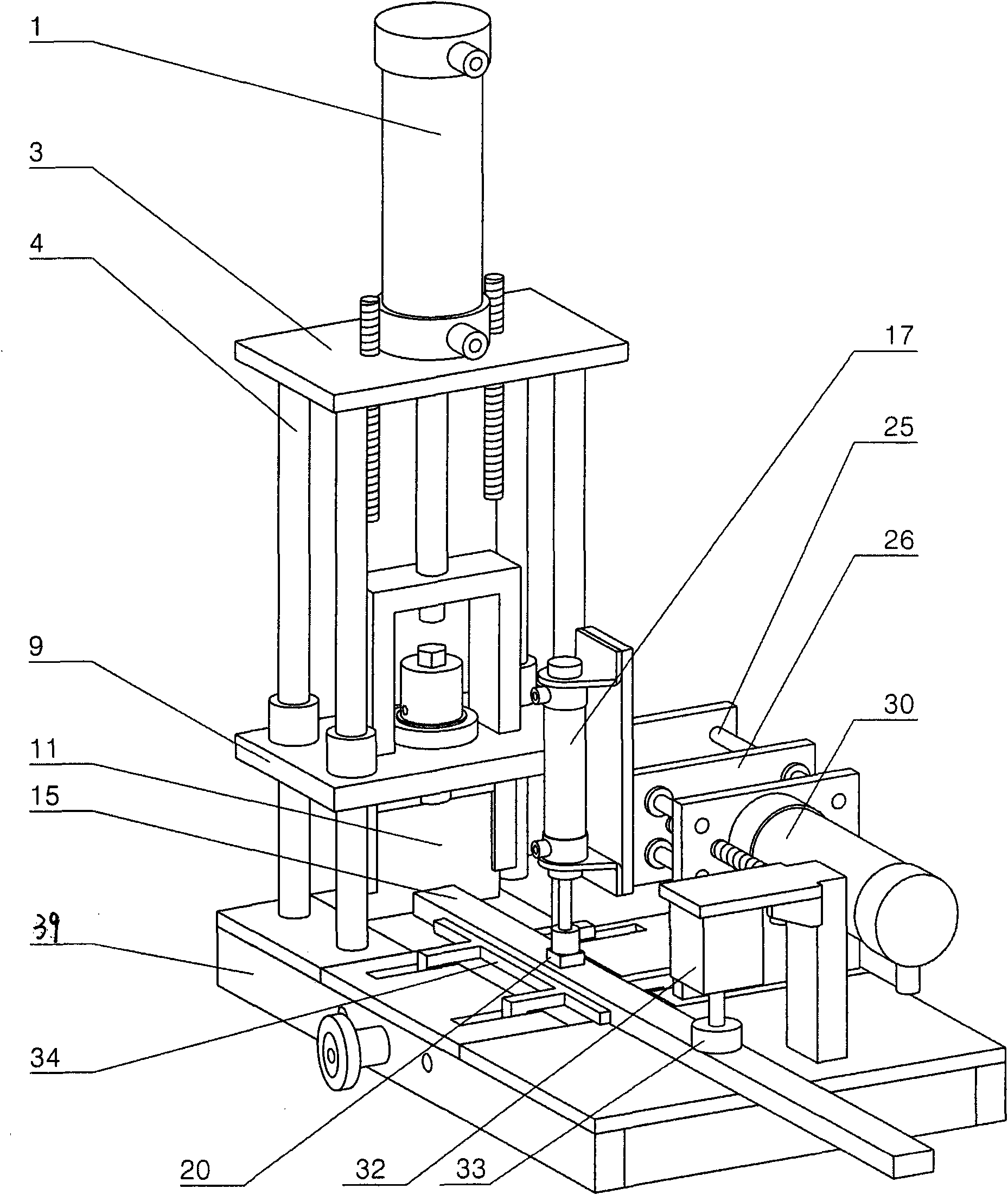
[0021] Such as figure 1 As shown, the present embodiment consists of a frame, a frame panel, a cutter mechanism, a push structure, a pressing mechanism, a limit mechanism, a base, an air control system, and an electric control system. The above-mentioned cutter mechanism bottom plate 13, air distribution Panel 18 , cover plate 21 , pushing mechanism bottom plate 22 and pressing mechanism bottom plate 23 constitute the frame panel together, and are installed on the frame 39 together. The power sources are respectively corresponding cylinders.

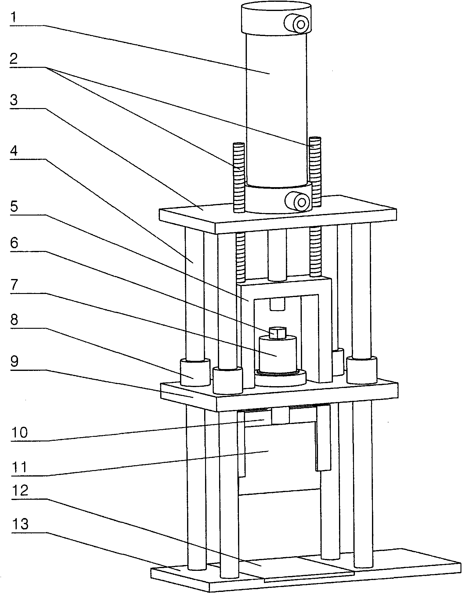
[0022] Such as figure 2 As shown, the described cutter mechanism is: the cutter cylinder frame is fixed on the frame panel, the cutter cylinder 1 is fixed on the cutter cylinder frame, and the piston head of the cutter cylinder 1 fixes the cutter 11. Specifically, the cutter mechanism includes a cutter cylinder 1, and the cutter cylinder 1 is fixed on the cutter cylinder fixed plate 3, and its cutter cylinder piston rod stretches out ...

Embodiment 2

[0044] In this embodiment, a polyurethane rubber or polytetrafluoroethylene material cutter backing plate 12 is fixed on the bottom plate 13 of the cutter mechanism facing the cutter 11. When the cutter cylinder 1 stretches out to the limit, the cutter 11 should Can cut into the thickness of cutter backing plate 12 about 0.2-1mm.

[0045] Other technical features and working principles are the same as in Embodiment 1.

Embodiment 3

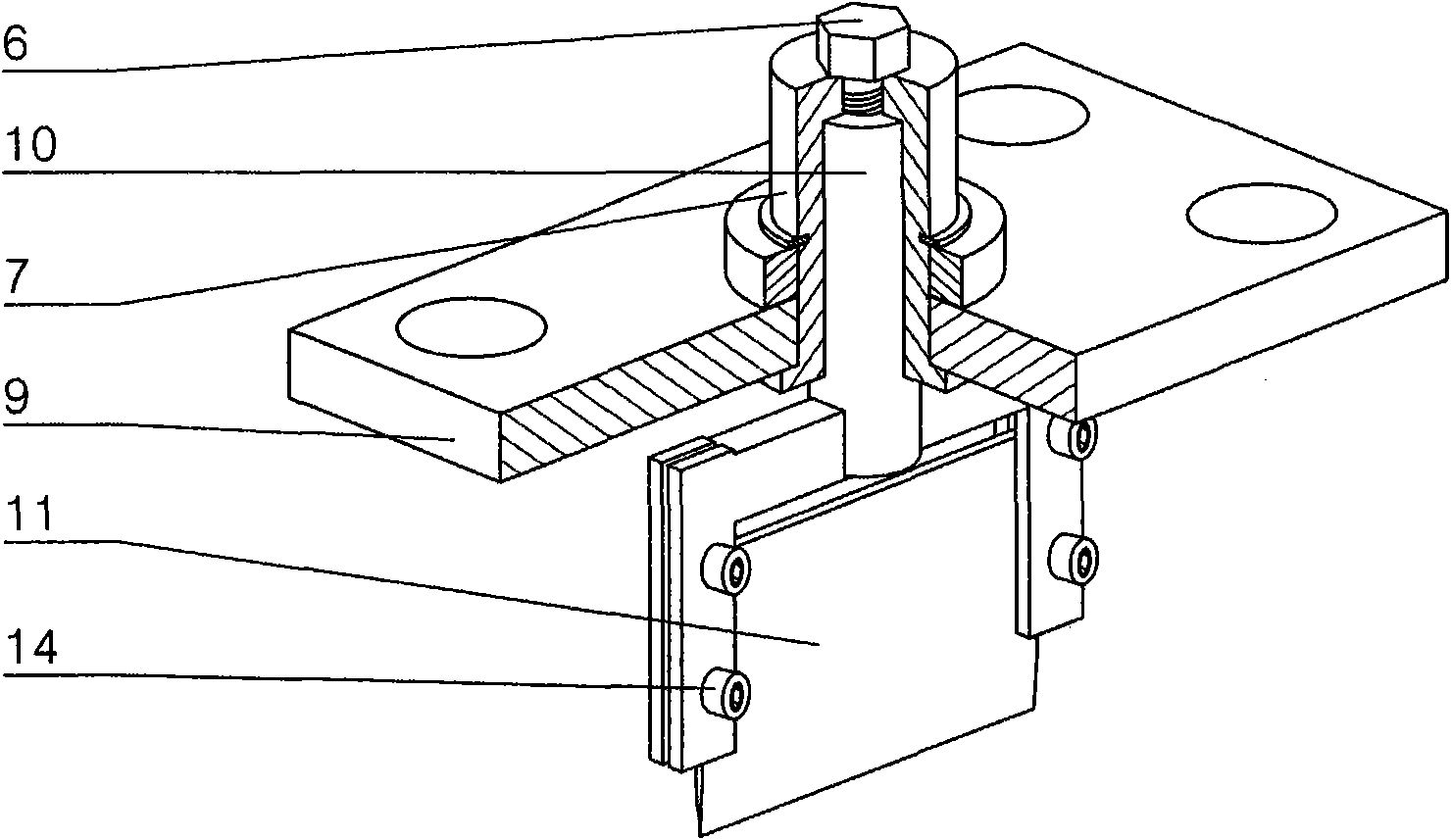
[0047] In this example, if Figure 5 As shown, the limiting mechanism includes two symmetrically arranged limiting plates 34, two circular holes are respectively arranged on the two limiting plates 34, and two round rods 35 pass through the circular holes, and the two round rods 35 have two circular holes. End is fixed on the frame 39. Also respectively have a threaded hole on the two limiting plates 34, one end of the adjusting screw mandrel 38 is screwed in to cooperate with it, and its other end passes through the round hole at the corresponding position on the frame 39, and the adjusting handwheel 37 and the retaining ring are installed. 36, thereby constraining the axial position of the adjusting screw rod 38, and turning the adjusting hand wheel 37 can drive the limit plate 34 to adjust its axial position on the round rod 35.

[0048] Other technical features and working principles are the same as in Embodiment 1.


PUM


Abstract

The invention discloses a pneumatic rubber cutting device which comprises a frame, wherein a cutter mechanism, a push mechanism, a press mechanism and a limit mechanism are arranged on the frame, andair cylinders respectively corresponding to the mechanisms are used as power sources. In the pneumatic rubber cutting device adopting the technical scheme, a piston of a cutter air cylinder of which the stroke can be adjusted can drive a cutter to do cutting actions; actions of a piston of a push air cylinder of which the stroke can be adjusted can drive a press head air cylinder fixed on a presshead air cylinder seat plate; and the press head air cylinder can drive a friction piece to press a strip rubber blank onto an air distribution panel. When the air distribution panel is pressed, an air cushion layer is formed between the air distribution panel and the upper plane of the strip rubber blank so as to ensure that friction force becomes quite small. A press air cylinder drives a presshead to press the strip rubber blank, and the limit mechanism carries out transverse limit on the strip rubber blank. A pneumatic control system and an electric control system control each air cylinder to cyclically act according to a certain order so as to cut the strip rubber blank, thereby overcoming the defect of poor cutting accuracy of a mechanical type transmission rubber cutting mechanismat present.

Description

technical field [0001] The invention belongs to the field of stationery manufacturing, and relates to a pneumatic rubber cutting machine, in particular to a device for cutting strip blanks produced by extruding plastic or rubber erasers, and can also be used for other continuous strips of cropping. Background technique [0002] At present, students, office plastics or rubber erasers are mainly square. The production method is that the raw material is extruded through an extruder to form a continuous long billet, and after cooling, it is cut into sections by a cutting machine, and the finished product is printed or not printed. At present, the cutting mechanisms used in the stationery industry are all mechanical transmissions, which drive the cutter mechanism and the conveying mechanism after driving the reducer through an electromagnetic speed regulating motor or a frequency conversion speed regulating motor. The cutter mechanism is a cutter driven by a crankshaft connecti...

Claims


Application Information

Patent Timeline
Patent Type & Authority Applications(China)
IPC IPC(8): B26D5/12B65H20/00B65H35/06B26D7/02B26D7/26B26D7/20B26D1/08
Inventor 宋卫兵张枭
Owner LUOHE LOUFOR STATIONERY MFG
Why Eureka
Try Eureka