Submerged-entry nozzle centring device

一种注入口、浸入式的技术,应用在金属加工设备、铸造设备、铸造熔融物容器等方向,能够解决损毁设备、增大工人安全事故、钢坯爆裂等问题,达到确保操作安全性、提高制造效率、提高质量的效果

Inactive Publication Date: 2010-03-31
HYUNDAE STEEL CO LTD
View PDF0 Cites 3 Cited by
  • Summary
  • Abstract
  • Description
  • Claims
  • Application Information

AI Technical Summary

Problems solved by technology

[0012] There are cases where, for example, first, the center of the submerged sprue 5 is deviated from the center of the crystallizer 3 figure 1 The left side of A; Second, the center of the submerged injection port 5 is deviated from the center of the crystallizer 3 figure 1 The right side of B; Third, the submerged sprue 5 may be caused by inaccurate connection of the sprue connector 9 figure 1 Inclined as shown in C, or the submerged spout 5 is rotated when replacing the submerged sprue 5
[0013] The channeling of the molten steel S in the mold due to the center shift increases fluctuations on the surface of the molten steel or causes eddy currents, thereby causing the mold powder to remain in the molten steel S, resulting in non-uniform solidification
This non-uniform solidification produces a non-uniform solidified shell and leads to a reduction in the quality of the slab and, in severe cases, to breakout, where the slab bursts and molten steel flows out during casting
[0014] Breakouts will increase the possibility of workers having safety accidents and damaging equipment
In addition, when equipment is damaged, the entire operation must be stopped, and the operating equipment must be reset, which reduces manufacturing efficiency

Method used


Image

  • Submerged-entry nozzle centring device
  • Submerged-entry nozzle centring device
  • Submerged-entry nozzle centring device

Examples


Embodiment Construction

[0032] A preferred embodiment of the device for centering the submerged sprue according to the present invention will be described in detail below with reference to the accompanying drawings.

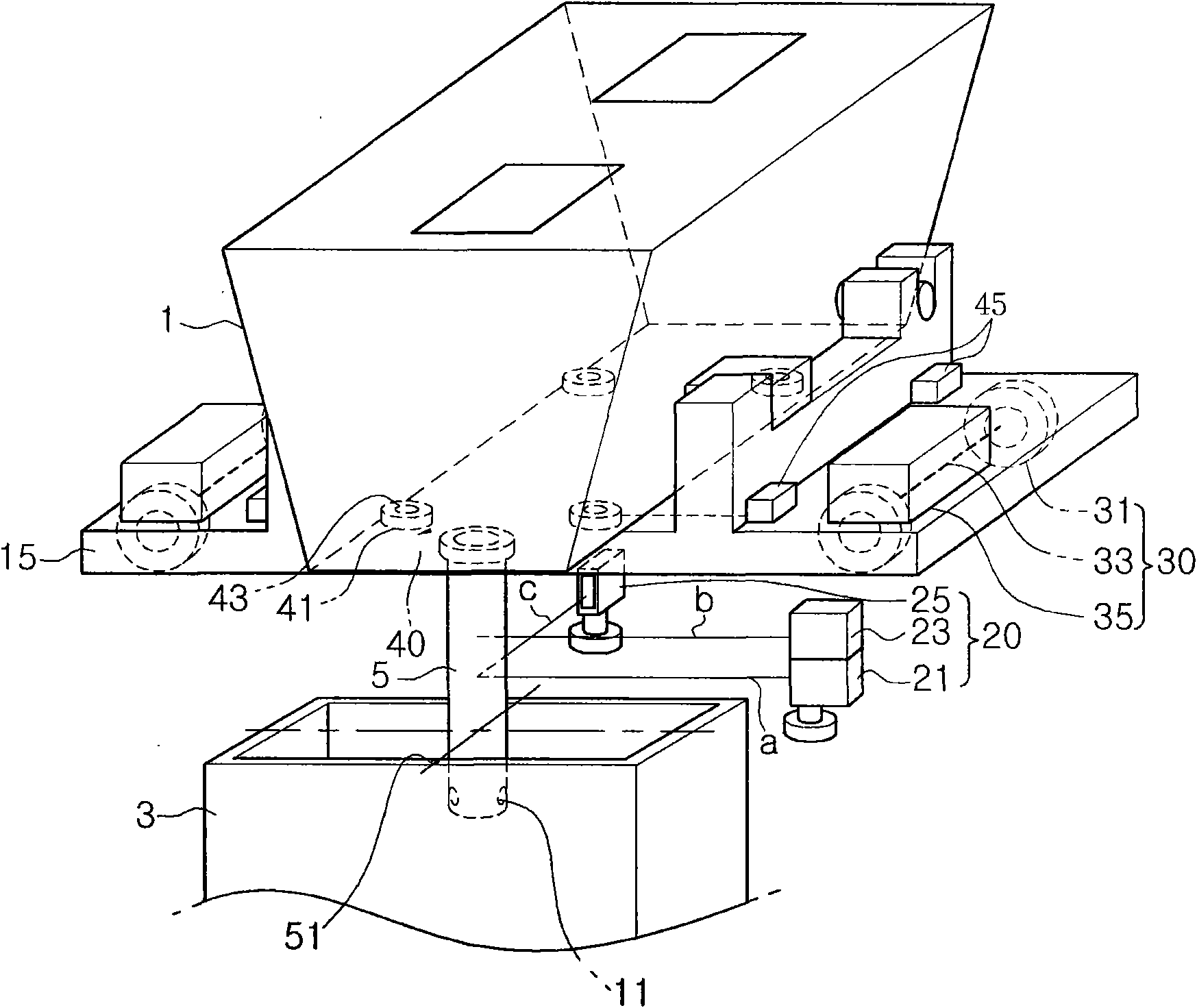
[0033] image 3 is a perspective view showing the construction of a preferred embodiment of the apparatus for centering a submerged sprue according to the present invention. The same structure as the prior art consists of figure 1 indicated by the reference numerals shown in .

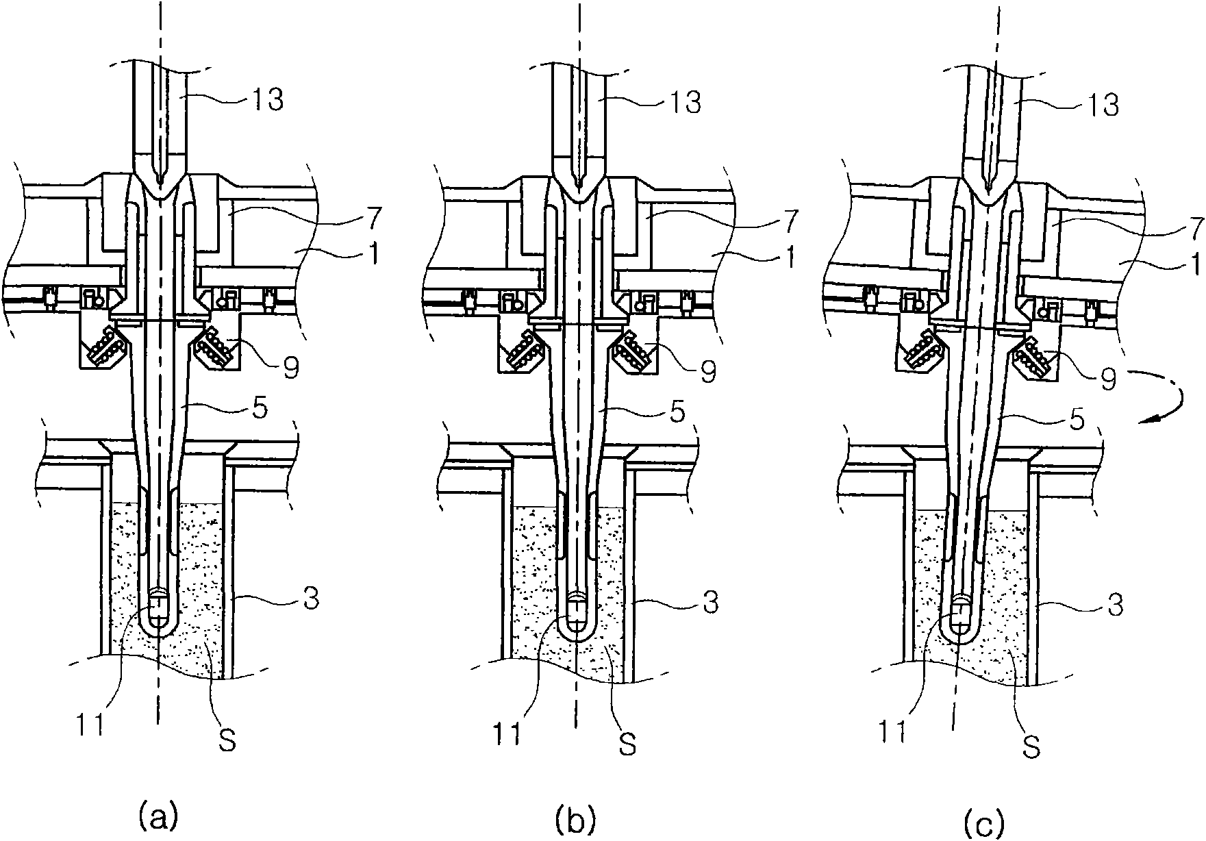
[0034] Before describing this embodiment below, it should be noted that the submerged sprue 5 is connected with the lower part of the tundish 1 through the sprue connector 9, and is inserted into the crystallizer 3 arranged below the tundish 1, so that the molten steel Inject from tundish 1 into crystallizer 3 . In addition, two molten steel outflow holes 11 are oppositely formed at the lower part of the submerged sprue 5 so as to supply the molten steel in the tundish 1 into the mold 3, centering the submerg...


PUM


Abstract

The present invention relates to a submerged-entry nozzle centring device. The present invention comprises: a plurality of laser beam generators (20) arranged in such a way as to irradiate laser beams towards the centre of a continuous-casting mould (3) from the upper part of the mould (3); a tundish-conveying mechanism (15) for conveying a tundish (1) over the mould (3); and a control means which is connected to the laser beam generator (20), and which controls the operation of the tundish-conveying mechanism (15) in such a way as to centre the positioning of a submerged-entry nozzle (5) provided on the lower part of the tundish (1) by means of a signal received from the laser beam generator (20). The present invention can not only centre the submerged-entry nozzle (5) in a way which is both accurate and fast, but it can also maintain the submerged-entry nozzle (5) constantly fixed at the centre and can thus minimise the phenomenon of drifting of the molten steel. Consequently, it has the advantage that it can be expected to improve the quality of the slab.

Description

technical field [0001] The present invention relates to an apparatus for centering a submerged sprue, and in particular, the present invention relates to an apparatus for centering a submerged sprue which accurately measures and manipulates the feed of molten steel from a tundish to Central location of the submerged sprue in the crystallizer. Background technique [0002] The continuous casting process produces slabs by continuously feeding molten steel from a ladle into a mold and cooling the mold while temporarily storing molten steel in a tundish of a continuous casting machine. [0003] figure 1 is a cross-sectional view showing an example of improper positioning of a submerged sprue inserted down into a crystallizer, figure 2 A schematic diagram showing the results of numerical analysis of normal or abnormal channeling phenomena depending on the location of the submerged sprue. [0004] According to these figures, a submerged sprue 5 for feeding molten steel into th...

Claims


Application Information

Patent Timeline
Patent Type & Authority Applications(China)
IPC IPC(8): B22D41/56B22D11/00
CPCB22D41/56B22D11/041B22D11/16B22D11/185
Inventor 文洪佶李桂荣崔周兑安宰焕权孝重
Owner HYUNDAE STEEL CO LTD
Why Eureka
Try Eureka