Electrical plug connector as a fuel injector contact for vibration-resistant applications

A technology of electric plug connectors and contacts, which is applied in the direction of fuel injection devices, connections, parts of connection devices, etc., to achieve the effects of small contact resistance, reduced micro-motion, and stable contact resistance

Inactive Publication Date: 2010-03-31
ROBERT BOSCH GMBH
View PDF5 Cites 2 Cited by
  • Summary
  • Abstract
  • Description
  • Claims
  • Application Information

AI Technical Summary

Problems solved by technology

This situation results in the following: The magnet assembly is no longer energized, making jetting impossible

Method used


Image

  • Electrical plug connector as a fuel injector contact for vibration-resistant applications
  • Electrical plug connector as a fuel injector contact for vibration-resistant applications

Examples


Embodiment Construction

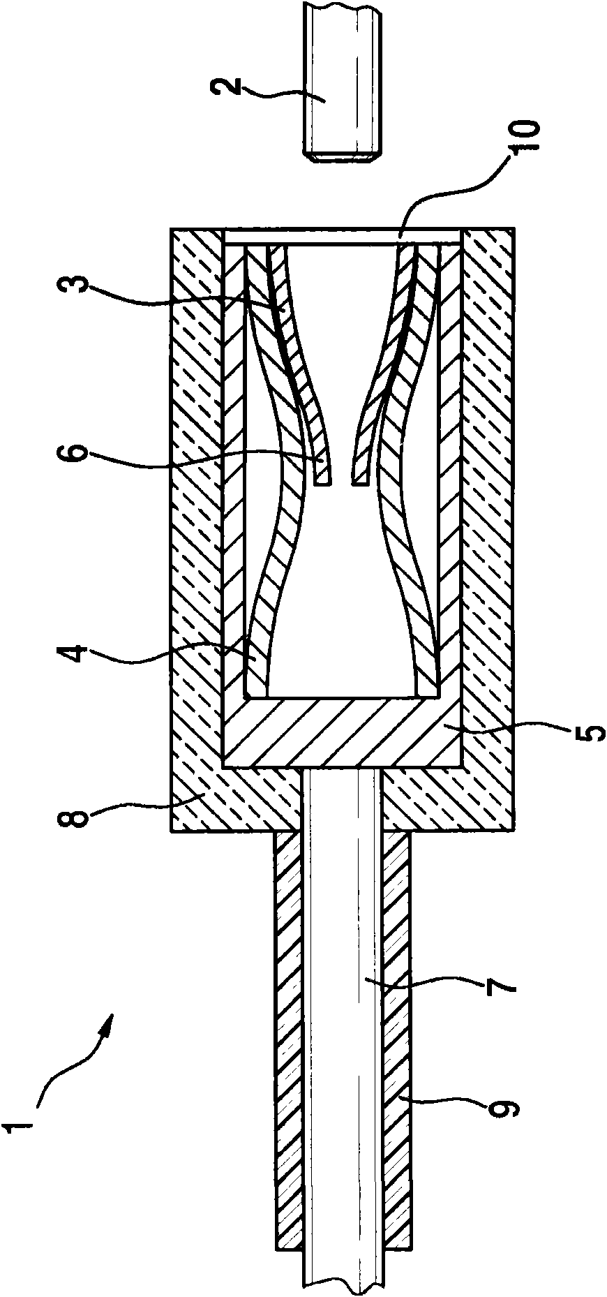
[0023] figure 1 The electrical connector 1 shown in is designed as a sleeve contact or a round contact for electrical contact with a pin plug 2 .

[0024] The electrical connector 1 comprises: a contact inner part 3 for electrical contact of the needle plug 2; an outer spring 4 enclosing the contact inner part 3; and a metal sleeve 5. The contact inner part 3 is made of nickel-nickel copper, preferably N18 (Wieland trade name), and in the shown embodiment is a longitudinally grooved circular sleeve with a plurality of inwardly directed contact fingers. (sheet) 6, and can be formed, for example, by a rolled sheet made of zinc-nickel-nickel copper. The contact interior part 3 has no surface coating, in particular no gold, silver or tin coating. The contact inner part 3 is clamped in an outer spring 4 made of stainless spring steel (for example 1.4310 with a strength of 1500 MPa). The outer spring 4 is installed in a metal sleeve 5 made of brass, for example, and clamped there...


PUM

PropertyMeasurementUnit
diameteraaaaaaaaaa
strengthaaaaaaaaaa

Abstract

An electrical plug connector (1) in the form of a socket contact with a contact inner part (3) for making electrical contact with a pin (2), and with an outer spring (4) which surrounds the contact inner part (3), the contact inner part (3) is, according to the invention, formed from nickel silver.

Description

Background technique [0001] The invention relates to an electrical plug connector according to the preamble of claim 1 . [0002] DE 102 48 809 A1, for example, discloses a plug contact that is commonly used in the automotive sector. [0003] DE 102 48 809 A1 describes an electrical plug-in connector in the form of a sleeve contact subjected to vibration loads for realizing an electrical plug-in connection in the automotive sector. This electrical plug connector consists of a contact inner part and an outer spring. The built-in part itself contains contact lugs, which bear with a contact point on the mating part, in particular a measuring device. In order to ensure increased contact reliability by means of an optimal contact normal force on each contact lug even in the case of oblique, rather vibrating or oscillating counterparts, the contact insert has At least three directional contact strips, each of which has at least one contact point, for an electrical plug connection...

Claims


Application Information

Patent Timeline
Patent Type & Authority Applications(China)
IPC IPC(8): H01R13/03F02M51/00H01R13/187
CPCF02M51/005H01R13/18H01R13/111H01R13/03C22C9/02C22C9/06
Inventor R·A·特科拉尔P·雷贝因S·罗曼特纳M·弗莱格
Owner ROBERT BOSCH GMBH
Why Eureka
Try Eureka