
Cutting rotor

A technology for cutting rotors and rotors, which is applied in metal processing, grain processing, etc., can solve the problems of poor cutting effect and achieve good cutting effect and simple structure

Inactive Publication Date: 2010-04-14
合肥华升泵阀股份有限公司
View PDF0 Cites 0 Cited by
  • Summary
  • Abstract
  • Description
  • Claims
  • Application Information

AI Technical Summary

Problems solved by technology

However, the existing shearing and cutting pumps have poor cutting effect and need to be improved urgently

Method used


Image

  • Cutting rotor
  • Cutting rotor
  • Cutting rotor

Examples


Embodiment Construction

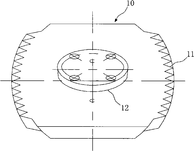
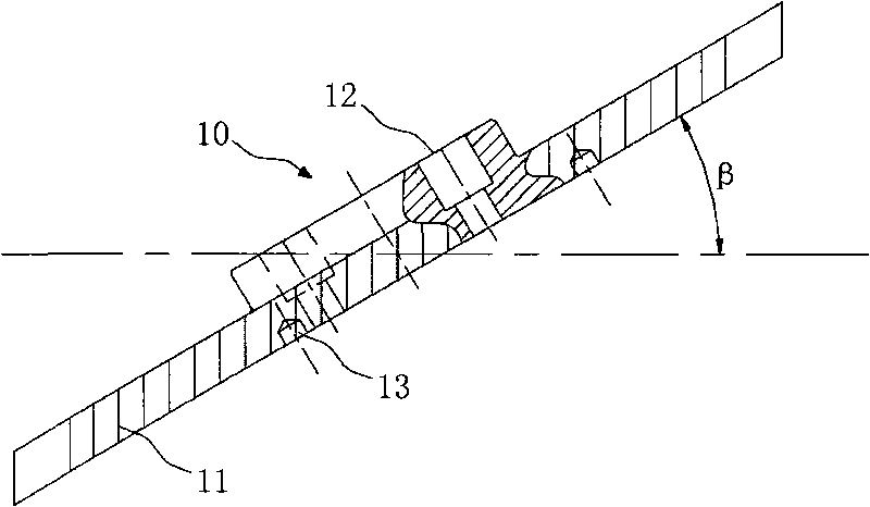
[0010] Such as figure 1 , 2 As shown in , 4, a cutting rotor, the rotor 10 is plate-shaped, the plate surface of the rotor 10 forms an angle β with the horizontal plane, and the side edge of the rotor 10 rotating around the horizontal line passing through the rotor plate surface is provided with teeth 11. The tooth tops of the teeth 11 are located on the same rotary surface, and the extension direction of the tooth tops of the teeth 11 is the same as the tangential direction of the rotary surface.

[0011] Further, the horizontal line around which the rotor 10 rotates is the horizontal projection line formed by the projection of the center line of symmetry of the rotor 10 on the horizontal plane. This rotation mode makes the rotation of the rotor 10 more stable and can obtain better cutting Effect.

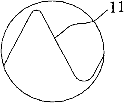
[0012] Such as image 3 As shown, the tooth top cross-section of the tooth 11 is arc-shaped, and this design of the tooth 11 is conducive to reducing the stress concentration p...


PUM

PropertyMeasurementUnit
Angleaaaaaaaaaa

Abstract

The invention belongs to the field of shearing and cutting pump technology, particularly relates to a cutting rotor. The rotor is plate-shaped, an included angle is formed between the plate surface of the rotor and a horizontal plane, teeth are arranged on the side edge of the rotor which rotates around a horizontal line passing through the plate surface of the rotor; the tops of the teeth are positioned at the same surface of revolution; and the extension direction of the tops of the teeth is identical to the tangential direction of the surface of revolution. Known from the technical scheme, the side edge of the rotor is provided with teeth, when the rotor rotates around a horizontal line passing through the plate surface of the rotor, the rotation locus of the teeth on the side edge of the rotor forms one surface of revolution, namely, the rotation locus of the teeth is the cutting locus of the teeth; and by the actions of acute fluid power abrasive cutting of the edges of the rotor, as well as tearing and extrusion and the like, the larger granules or impurities in the fluid body are torn and ground into smaller particles. Therefore, the cutting rotor is simple in structure and good in cutting effect.

Description

technical field [0001] The invention belongs to the technical field of shearing and cutting pumps, in particular to a cutting rotor. Background technique [0002] The tar slag cutting pump is one of the key equipment for tar processing in the iron and steel tar industry. It breaks up the large particle size tar slag and sends the crushed tar slag to the tar ammonia water separation tank. However, the existing shearing and cutting pumps have poor cutting effect and need to be improved urgently. Contents of the invention [0003] The object of the present invention is to provide a cutting rotor with simple structure and good cutting effect. [0004] In order to achieve the above object, the present invention adopts the following technical solutions: a cutting rotor, the rotor is plate-shaped, the plate surface of the rotor forms an angle with the horizontal plane, and the side edge of the rotor rotating around the horizontal line passing through the rotor plate surface Tee...

Claims


Application Information

Patent Timeline
IPC IPC(8): B02C18/16B26D7/00
Inventor 巫建波李强胡敬宁石海峡柴立平程道武宫恩祥朱维虎姜漫
Owner 合肥华升泵阀股份有限公司
Features
  • Generate Ideas
  • Intellectual Property
  • Life Sciences
  • Materials
  • Tech Scout
  • Unparalleled Data Quality
  • Higher Quality Content
  • 60% Fewer Hallucinations
Learn More