Novel LED die bonding method

A new type of crystal-bonding technology, applied in electrical components, circuits, semiconductor devices, etc., can solve problems such as insufficient light output from LEDs, achieve the effects of reducing coverage area, enhancing directivity, and increasing output rate

Inactive Publication Date: 2010-04-14
SUZHOU ZHONGZE OPTOELECTRONICS TECH
View PDF0 Cites 14 Cited by
  • Summary
  • Abstract
  • Description
  • Claims
  • Application Information

AI Technical Summary

Problems solved by technology

[0003] In order to solve the above-mentioned problem of insufficient LED light output, the prese

Method used


Image

  • Novel LED die bonding method
  • Novel LED die bonding method
  • Novel LED die bonding method

Examples


Embodiment Construction

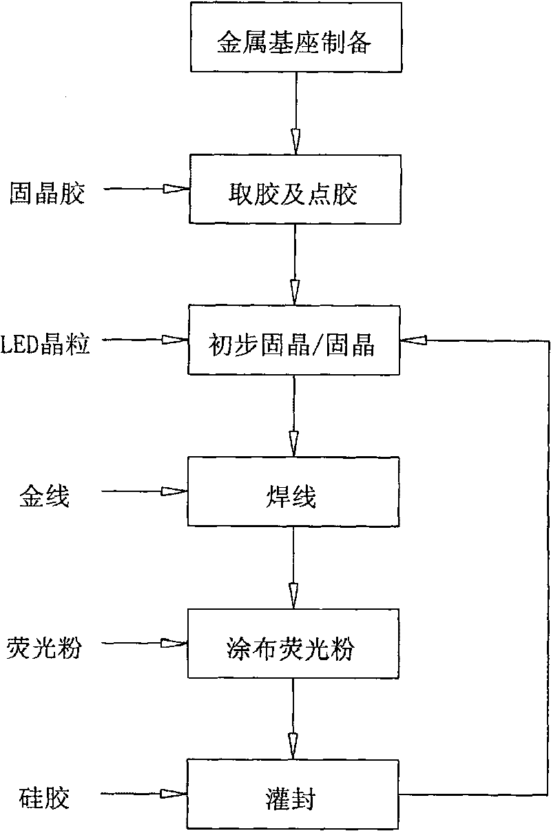
[0015] A method of bonding crystals to improve the light-emitting efficiency of LEDs, such as figure 1 The process shown includes: preparation of the metal base, glue removal and dispensing, preliminary die bonding, wire bonding, phosphor coating, and finally potting of silica gel for final die bonding. Wire bonding and phosphor coating are not steps for die bonding , but the entire process must be carried out step by step according to the above process, and the steps closely related to die bonding are described in detail below.

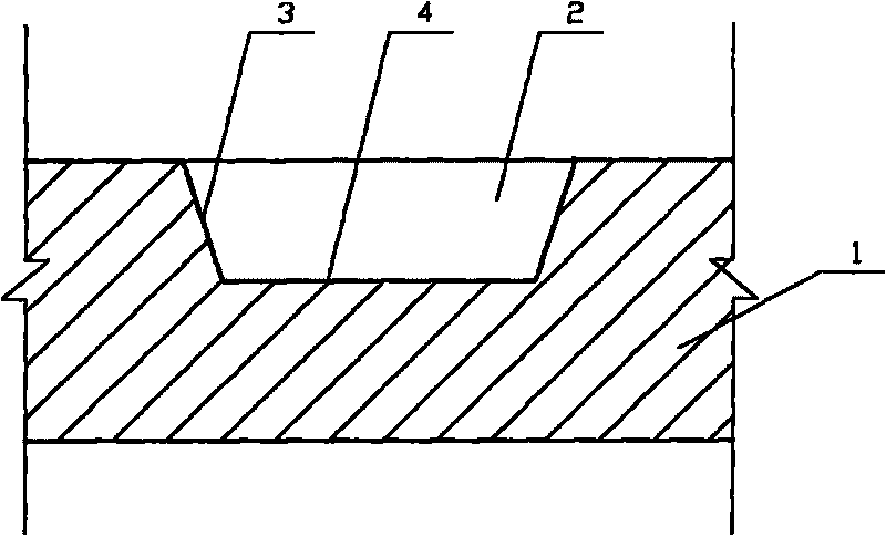
[0016] like figure 2 The metal base (1) is shown. The metal base is made of high thermal conductivity metal material, usually silver-plated on the surface of a copper plate. There are LED crystal grain fixing pits (2) arranged on the metal base, and the pits usually use a bell mouth shape, the inner surface of the bell mouth is polished and plated with a reflective layer (4), and the bottom surface of the pit is a solid crystal surface (4).
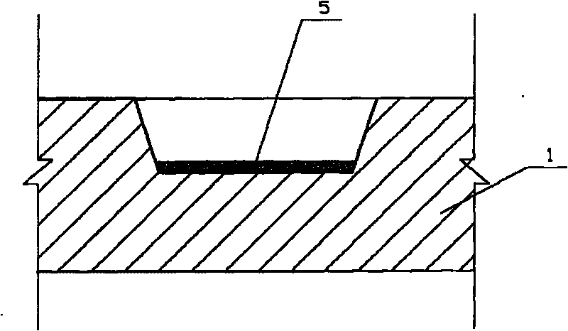
[001...


PUM


Abstract

The invention relates to a novel LED die bonding method which comprises the steps: firstly, coating a thin layer of die bonding glue on a bottom die bonding surface of a LED crystal particle fixing concave pit with a reflection layer on a metal base; after completion, placing the LED crystal particles at a base die bonding surface dispensed with die bonding glue, compacting and completing primary die bonding, then welding gold thread, coating fluorescent powder, and finally encapsulating by silica gel so as to wholly wrap LED crystal particles in the silica gel, thus completing final die bonding. The traditional LED carry out die bonding by the die bonding glue, while in the invention, only a thin layer of die bonding glue is coated for playing a role of primary die bonding, and finally the die bonding protection is carried out by encapsulating the silica gel. The method does not influence LED solid luminescence, and the light emitted from the periphery thereof is reflected out by the fixing concave pit, thus improving light extraction efficiency.

Description

technical field [0001] The invention relates to the field of LED crystal grain packaging, to be precise, it is a novel crystal bonding method. Background technique [0002] Die-bonding technology is one of the key technologies in the field of LED packaging. The quality of the die-bonding will affect the stability, heat dissipation efficiency and light output efficiency of the LED. The difference is that, generally speaking, the small-power LED grains can be heat-conducted by fixing the electrode pins with insulating glue; LEDs with slightly higher power can be dissipated by heat-conducting silver glue or silica gel; for watt-level LEDs, high-heat-conducting silver glue or Eutectic soldering is used to fix heat dissipation. The currently commonly used thermally conductive adhesive die-bonding method often wraps a part of the LED die in the die-bonding adhesive due to problems such as the amount of glue used, the uniformity of application, and the fixation force, which affects...

Claims


Application Information

Patent Timeline
IPC IPC(8): H01L33/00
Inventor 黄金鹿黄莺缪应明吴海生
Owner SUZHOU ZHONGZE OPTOELECTRONICS TECH
Why Eureka
Try Eureka