Hydraulic power chuck controlled by electro-hydraulic proportional pressure valve

An electro-hydraulic proportional and hydraulic power technology, applied in the direction of the chuck, can solve the problems of low initial clamping force of the power chuck, damage to the surface quality of the workpiece, damage to the finished workpiece, etc., to achieve reliable clamping, meet high-speed cutting, The effect of improving the control precision

Inactive Publication Date: 2010-04-21
ZHEJIANG UNIV
View PDF0 Cites 6 Cited by
  • Summary
  • Abstract
  • Description
  • Claims
  • Application Information

AI Technical Summary

Problems solved by technology

However, in finishing machining, excessive initial clamping force will damage the surface quality of the workpiece, and materials that are easily deformed, such as copper, aluminum, and engineering plastics, will be clamped under the action of a large initial clamping force.
[0004] When the hydraulic power chuck clamps the inner hole of the workpiece, the clamping force increases with the increase of the rotating speed. Excessive clamping force will also damage the finished and easy-to-deform workpieces, and too low initial oil supply pressure will cause The initial clamping force of the power chuck is too low and the clamping is not reliable
[0005] In precision high-speed turning and high-speed turning of easily deformed workpieces, how to make the hydraulic power chuck not only reliably clamp the workpiece, but also achieve high speed is a difficult problem. Traditional technical solutions cannot solve this problem.

Method used


Image

  • Hydraulic power chuck controlled by electro-hydraulic proportional pressure valve
  • Hydraulic power chuck controlled by electro-hydraulic proportional pressure valve
  • Hydraulic power chuck controlled by electro-hydraulic proportional pressure valve

Examples


Embodiment Construction

[0019] The present invention will be further illustrated by the accompanying drawings and examples.

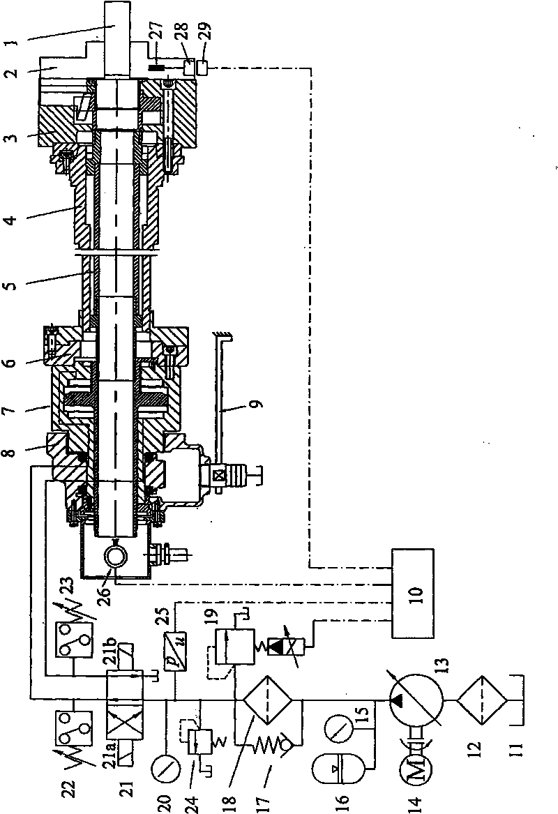
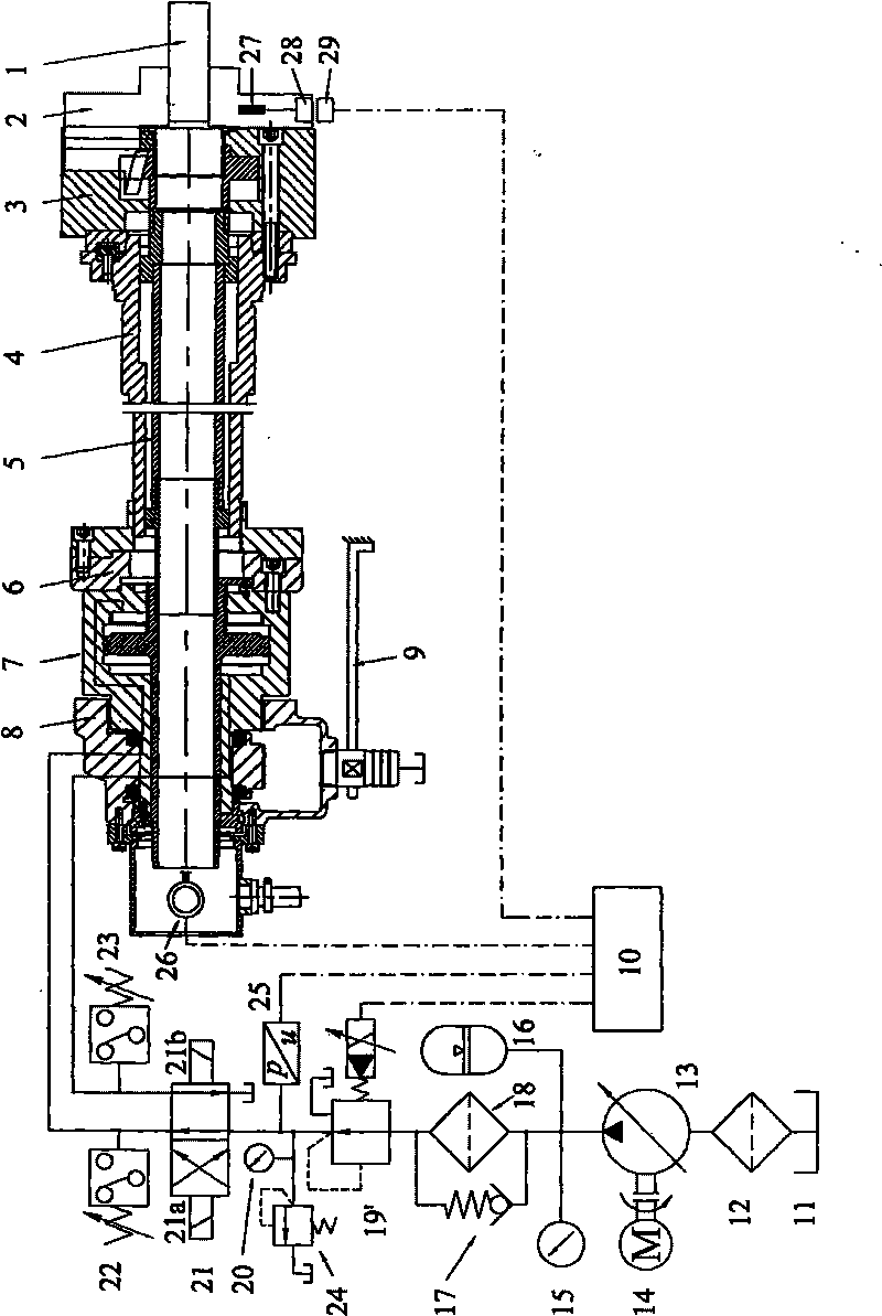
[0020] The first embodiment of the present invention is figure 1 As shown, the present invention comprises a hydraulic power chuck, a hydraulic pump station composed of an oil supply device, an oil pressure regulator, an oil supply direction control device, and an oil supply pressure monitoring device, and a signal acquisition control system; the hydraulic power chuck is composed of a power chuck The disk 3 and the rotary hydraulic cylinder 7 are composed of the power chuck 3 connected with the front end of the lathe spindle 4, the rotary hydraulic cylinder 7 is connected with the tail end of the lathe spindle 4 through the transition flange 6, and the two ends of the pull pipe 5 are respectively connected with the rotary hydraulic cylinder. The piston rod of 7 is connected to the wedge sleeve of the power chuck 3, the rotary hydraulic cylinder 7 drives the power chuck 3 to cl...


PUM


Abstract

The invention discloses a hydraulic power chuck controlled by an electro-hydraulic proportional pressure valve, comprising a hydraulic power chuck, a hydraulic pump station and a signal collection and control system, wherein the hydraulic pump station consists of an oil supply device, an oil pressure adjusting device, an oil supply direction control device and an oil supply pressure monitoring device. The oil pressure adjusting device is realized by adopting an electro-hydraulic proportional overflow valve or an electro-hydraulic proportional reducing valve; the signal collection and control system comprises a controller and a rotate speed transducer arranged at the end part of a lathe main shaft; and a control electrical signal end of the rotating speed transducer and a control electrical signal end of the electro-hydraulic proportional overflow valve or the electro-hydraulic proportional reducing valve are respectively and electrically connected with a controller. When the lathe main shaft changes speed, the output oil pressure of the hydraulic pump station and the oil supply pressure of a rotation hydraulic cylinder can be regulated in a stepless mode so as to keep the clamping force of the hydraulic power chuck constant. When the hydraulic power chuck is used for clamping finish machining workpieces or easily deformed workpieces, both reliable clamping and high rotate speed can be realized, and requirement of high-speed cutting can be satisfied.

Description

technical field [0001] The invention relates to a clamping device of a machine tool, in particular to a hydraulic power chuck controlled by an electro-hydraulic proportional pressure valve. Background technique [0002] The hydraulic power chuck is the workpiece fixture of the CNC lathe, which is composed of a rotary hydraulic cylinder and a power chuck. The oil supply pressure of the traditional hydraulic power chuck is adjusted by a manually adjustable pressure reducing valve or relief valve. After the oil supply pressure is initially set, it remains constant during the rotation of the spindle. The centrifugal force of the claws increases, and the clamping force decreases when the power chuck clamps the outer circle of the workpiece. The loss of clamping force limits the increase of the hydraulic power chuck's speed. [0003] It is an effective way to increase the speed of the hydraulic power chuck by increasing the initial oil supply pressure and increasing the initial c...

Claims


Application Information

Patent Timeline
Patent Type & Authority Applications(China)
IPC IPC(8): B23B31/08
Inventor 杨华勇周城杨利奎
Owner ZHEJIANG UNIV
Why Eureka
Try Eureka