Photoelectric device of distributed optical fiber temperature sensing system

A technology of distributed optical fiber and sensing system, which is applied to the coupling of thermometers, measuring devices, and optical waveguides, etc. It can solve the problems of line layout, stability of circuit parts, and influence on accuracy, and achieve low cost and good stability. and accuracy, light weight effect

Inactive Publication Date: 2010-04-21
SHANGHAI BOOM FIBER SENSING TECH +1
View PDF1 Cites 27 Cited by
  • Summary
  • Abstract
  • Description
  • Claims
  • Application Information

AI Technical Summary

Problems solved by technology

[0004] However, in the distributed optical fiber temperature sensing system, the optical path part and the light receiving circuit part are usually arranged in a decentralized manner, and a large number of wiring problems will arise when the system is arranged. When running the entire system, the optical path part and the light receiving circuit part The stability and accuracy of the circuit part will also be affected

Method used


Image

  • Photoelectric device of distributed optical fiber temperature sensing system
  • Photoelectric device of distributed optical fiber temperature sensing system
  • Photoelectric device of distributed optical fiber temperature sensing system

Examples


Embodiment Construction

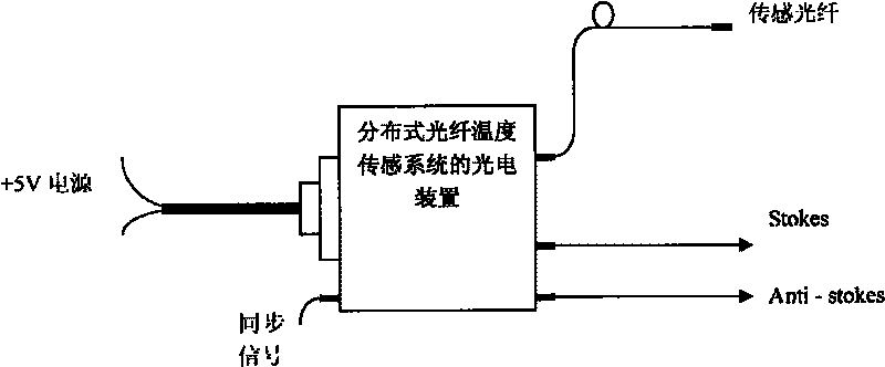
[0039] The specific implementation steps of the present invention will be further described below in conjunction with the accompanying drawings. In this embodiment, the model of the optoelectronic device of the distributed optical fiber temperature sensing system is as follows figure 1 As shown, it includes the sensor fiber input port, the Anti-stokes electrical signal output port, the Stokes electrical signal output port, and the synchronization signal output port.

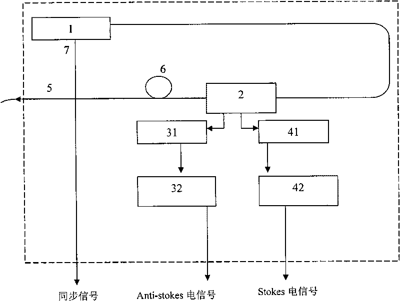
[0040] figure 2 It is a schematic diagram of the overall structure of the device, which includes: a laser 1, a fiber Raman-WDM coupler 2, a first light receiving module 31, a second light receiving module 41, a first amplification matching circuit 32, and a second amplification matching circuit 42;

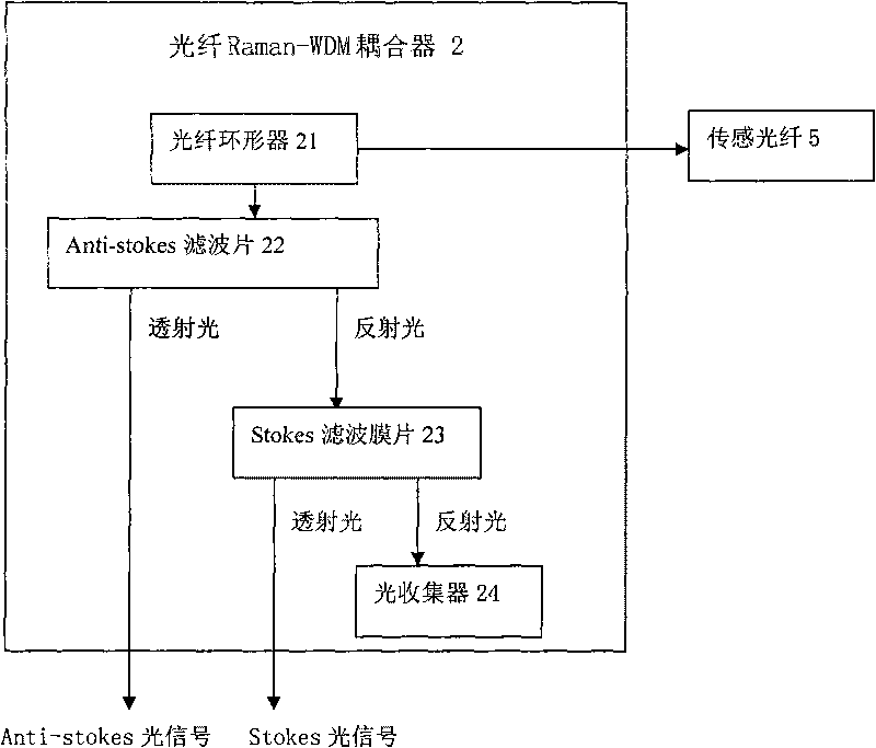
[0041] The fiber Raman-WDM coupler 2 includes an input port, a feedback port and two output ports for obtaining Anti-stokes optical signal and Stokes optical signal; the output port of the laser 1 is connected with...


PUM


Abstract

The invention discloses a photoelectric device of a distributed optical fiber temperature sensing system. The photoelectric device comprises a laser, an optical fiber Raman-WDM coupler, a first optical receiving module, a second optical receiving module, a first amplification matching circuit and a second amplification matching circuit, wherein the output end of the laser is connected with the input end of the optical fiber Raman-WDM coupler through an optical fiber; a feedback end of the optical fiber Raman-WDM coupler is connected with a sensing optical fiber; two output ends of the optical fiber Raman-WDM coupler are respectively connected with the first optical receiving module and the second optical receiving module; the first optical receiving module is connected with the first amplification matching circuit; and the second optical receiving module is connected with the second amplification matching circuit. The photoelectric device is used for generating optical pulses to convert backward Raman scattering optical signals carrying temperature information in the sensing optical fiber into electric signals and output the electric signals.

Description

technical field [0001] The invention relates to an optical fiber temperature sensing device, in particular to a device integrating an optical path and a light receiving circuit of a distributed optical fiber temperature sensing system, and belongs to the field of optical fiber sensing. Background technique [0002] Distributed optical fiber temperature sensing system is a high-tech product used to measure the distribution of spatial temperature field in real time. We can continuously measure the temperature of various points within several kilometers along the optical fiber in real time, the spatial resolution is 1 meter, the positioning accuracy is on the order of 1 meter, and the temperature measurement accuracy can reach the level of 1 degree, which is very suitable for large-scale multi-point temperature measurement application occasions. Therefore, this kind of fiber optic sensor has a wide range of applications in the temperature fixed-point sensing of high-voltage po...

Claims


Application Information

Patent Timeline
Patent Type & Authority Applications(China)
IPC IPC(8): G01K11/32G02B6/42G01K11/324
Inventor 杨斌刘亮皋魏席刚周正仙仝芳轩
Owner SHANGHAI BOOM FIBER SENSING TECH
Why Eureka
Try Eureka