System and method for diagnosing faults of numerical control machine

A fault diagnosis system, CNC machine tool technology, applied in general control systems, control/regulation systems, program control, etc., can solve problems such as time-consuming, distortion or attenuation, complex processes, etc., achieve simple hardware structure, improve operating efficiency, The effect of reducing downtime for maintenance

Inactive Publication Date: 2010-04-21
SHANGHAI SECOND POLYTECHNIC UNIVERSITY
View PDF1 Cites 25 Cited by
  • Summary
  • Abstract
  • Description
  • Claims
  • Application Information

AI Technical Summary

Problems solved by technology

This kind of device involves more complex circuits, and the signal undergoes multi-level conditioning and conversion, which is easy to cause distortion or attenuation, and the process is complicated and time-consuming
In addition, this device only uses the grinding machine as the object of fault diagnosis

Method used


Image

  • System and method for diagnosing faults of numerical control machine
  • System and method for diagnosing faults of numerical control machine

Examples


Embodiment 1

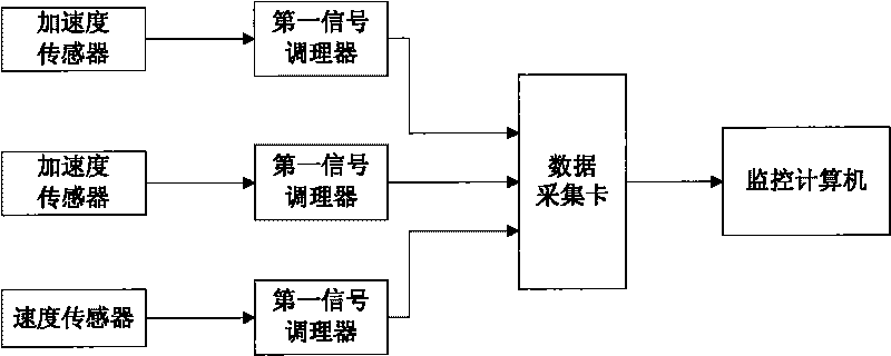
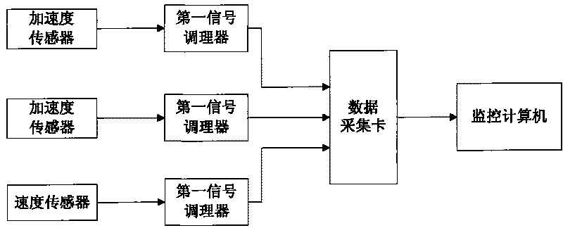
[0026] Such as figure 1 As shown, a CNC machine tool fault diagnosis system includes:

[0027] Two acceleration sensors and one speed sensor are used to obtain vibration signals generated by CNC machine tools;

[0028] Two first signal conditioners are respectively connected to the output end of one of the acceleration sensors, and are used to condition and output the signals output by the acceleration sensors;

[0029] The second signal conditioner is connected to the output terminal of the speed sensor, and is used for conditioning and outputting the signal output by the speed sensor;

[0030] A data acquisition card, connected to the first signal conditioner and the second signal conditioner, for collecting and outputting the signal outputted by the first signal conditioner and the second signal conditioner after conditioning;

[0031] The monitoring computer is connected with the output end of the data acquisition card, and is used to calculate and analyze the vibration ...

Embodiment 2

[0036] A method for fault diagnosis of a numerically controlled machine tool, comprising the following steps:

[0037] 1) The vibration signal acquisition step is to obtain the vibration signal generated by the CNC machine tool through two acceleration sensors and a speed sensor;

[0038] 2) a signal conditioning step, conditioning and outputting the signal output by the acceleration sensor through two first signal conditioners; conditioning and outputting the signal output by the speed sensor through a second signal conditioner;

[0039] 3) a data collection step, for collecting and outputting signals output by the first signal conditioner and the second signal conditioner after conditioning;

[0040] 4) The signal analysis step is used to calculate and analyze the vibration signal generated by the CNC machine tool, so as to realize the intelligent fault diagnosis of the machine tool.

[0041] Among them, the specific analysis method may be to analyze the vibration signal in...


PUM


Abstract

The invention relates to a system and a method for diagnosing faults of a numerical control machine. The system comprises two acceleration sensors and one speed sensor which are used for obtaining vibration signals generated by the numerical control machine, two first signal conditioners used for conditioning and outputting signals output by the acceleration sensors, a data acquisition card used for gathering signals which are output after being conditioned, a monitoring computer connected with the output end of the data acquisition card and used for calculating and analyzing the vibration signals generated by the numerical control machine and diagnosing faults of the numerical control machine. The method comprises the following steps: (1) obtaining vibration signals; (2) conditioning the signals; (3) gathering data; and (4) analyzing the signals. The device has simple hardware structure and realizes the diagnosing and analyzing function mainly based on software, thereby being convenient to update and maintain. The fault time of the machine is reduced, thereby enhancing the operation efficiency of the machine in processing.

Description

technical field [0001] The invention belongs to the technical field of numerical control machine tool fault diagnosis, in particular to a numerical control machine tool fault diagnosis system and method thereof. Background technique [0002] In the field of modern mechanical processing, CNC machining has occupied a dominant position, especially for processing parts with large quantities and high precision requirements, various CNC machine tools play an irreplaceable role. Therefore, the working stability and reliability of CNC machine tools are of great significance for improving the production efficiency of enterprises. Using the vibration signal generated when the machine tool is processing, the current running status of the CNC machine tool can be analyzed, and intelligent fault diagnosis can be carried out in advance, so as to avoid the need to stop for a long time for maintenance once a fault occurs. [0003] Through literature search, it is found that the Chinese inve...

Claims


Application Information

Patent Timeline
Patent Type & Authority Applications(China)
IPC IPC(8): G05B19/406B23Q17/00
Inventor 安双利
Owner SHANGHAI SECOND POLYTECHNIC UNIVERSITY
Why Eureka
Try Eureka