Controllable electromagnetic coupling dielectric resonator filter

A dielectric resonator and electromagnetic coupling technology, applied in circuits, electrical components, waveguide devices, etc., can solve the problems that the main coupling filter cannot realize the elliptic function filtering characteristics, and the volume of the cross-coupling filter is large, so as to achieve flexible transmission zero point settings, easy filter response, small volume effects

Inactive Publication Date: 2010-04-28
SOUTH CHINA UNIV OF TECH
View PDF1 Cites 13 Cited by
  • Summary
  • Abstract
  • Description
  • Claims
  • Application Information

AI Technical Summary

Problems solved by technology

[0006] The purpose of the present invention is to overcome the problem that the existing main coupling filter cannot realize the elliptic function filtering characteristics, overcome the problem that the volume of the existing cross-coupling filter is still large, and provide a dielectric resonat...

Method used


Image

  • Controllable electromagnetic coupling dielectric resonator filter
  • Controllable electromagnetic coupling dielectric resonator filter
  • Controllable electromagnetic coupling dielectric resonator filter

Examples


Embodiment

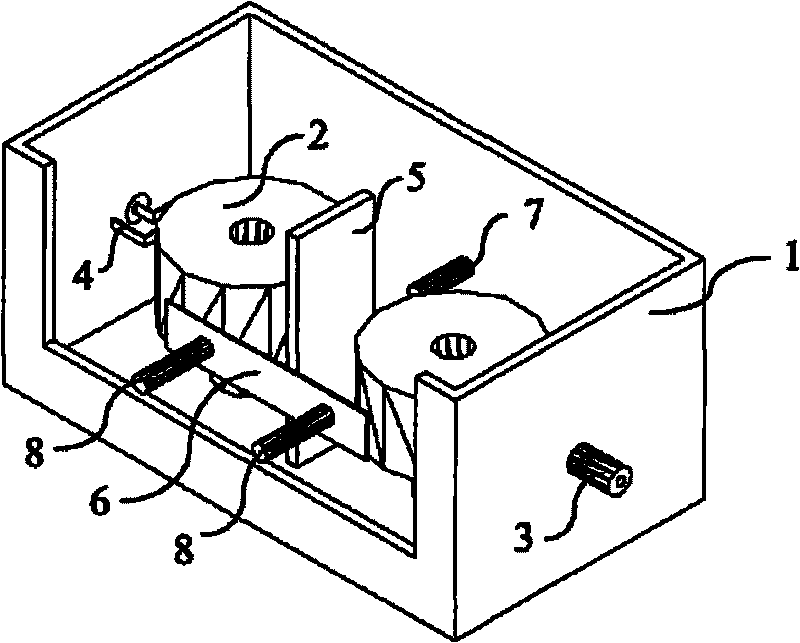
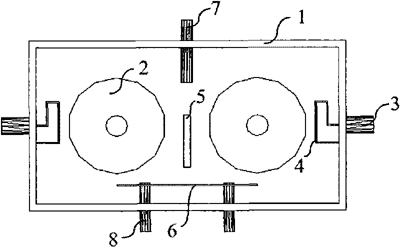
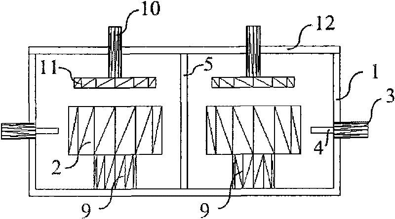
[0028] Figure 1 ~ Figure 3It is a structural schematic diagram of a controllable electromagnetic coupling dielectric resonator filter with 2nd order and 1 zero point. There are two dielectric resonators 2 inside the conductor shell 1 to form a controllable electromagnetic coupling unit. The top of the conductor case 1 is closed by the conductor cover 12, and the place around the conductor cover 12 in contact with the conductor case 1 is fixed by uniformly distributed metal screws. The input / output coaxial cable 3 passes through the conductor shell 1 and feeds electromagnetic energy into / out of the filter through the energy conversion device 4 . The energy conversion device shaft 4 can be a short-circuit metal ring with one end connected to the inner core of the feeding coaxial cable 3 and the other end connected to the conductor shell; it can also be one end connected to the inner core of the feeding coaxial cable 3, An open circuit metal probe whose other end does not touch...


PUM


Abstract

The invention discloses a controllable electromagnetic coupling dielectric resonator filter, which comprises a conductor shell, wherein two or more dielectric resonators which operate in a TE01 delta mode are arranged in the conductor shell; the top part of the conductor shell is closed by a conductor cover plate; an input/output device passes through the conductor shell to feed electromagnetic energy in the filter and discharge the electromagnetic energy out of the filter; a tuning screw is arranged on the conductor cover plate just opposite to the top part of the dielectric resonators; the bottom part of the tuning screw is connected with a tuning disc; and an electromagnetic coupling control component is arranged between two adjacent conductor dielectric resonators requiring controllable electromagnetic coupling. In the invention, an elliptic function filtration property is realized by using a coaxial cavity filter only having a main coupling path, and the controllable electromagnetic coupling dielectric resonator filter has the advantages of small volume, low cost, small plug-in consumption and asymmetric response.

Description

technical field [0001] The invention relates to a microwave filter, in particular to a dielectric resonator filter with a controllable electromagnetic coupling structure. Background technique [0002] With the continuous increase of wireless communication user capacity, the limited microwave frequency band becomes more and more crowded, and spectrum resources become more and more scarce and are divided into multiple sub-frequency bands more and more strictly and densely. Therefore, the growing market demand and the improvement of wireless communication standards urgently require microwave filters to have higher selectivity and lower loss so as to cut, divide and utilize limited spectrum resources more efficiently. Dielectric resonators are used to manufacture dielectric resonator filters with high selectivity, high stability, and low loss due to their extremely high Q value, dielectric constant, and temperature stability. Dielectric resonator filters have been widely used i...

Claims


Application Information

Patent Timeline
IPC IPC(8): H01P1/20
Inventor 褚庆昕王欢
Owner SOUTH CHINA UNIV OF TECH
Why Eureka
Try Eureka