Lens antenna

A lens antenna and lens technology, applied in antennas, electrical components, etc., can solve the problems of difficult processing and high surface precision requirements, and achieve the effects of flexible design, simple production, and flexibility.

Active Publication Date: 2010-04-28
SOUTHEAST UNIV
View PDF4 Cites 489 Cited by
  • Summary
  • Abstract
  • Description
  • Claims
  • Application Information

AI Technical Summary

Problems solved by technology

This kind of lens has high requirements on the accurac

Method used


Image

  • Lens antenna
  • Lens antenna
  • Lens antenna

Examples


Embodiment Construction

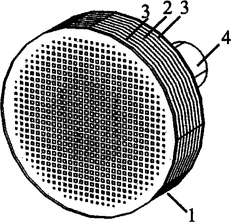
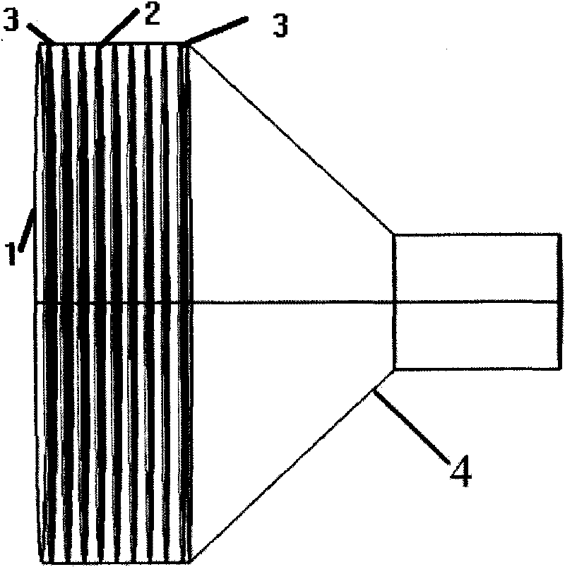
[0029] Such as figure 1 and figure 2 As shown, a kind of lens antenna of the present invention comprises metal horn 4 and lens 1 that feed source is housed, and this feed source is embedded in one end of metal horn 4 with smaller diameter, and lens 1 is embedded in metal horn 4 with larger diameter. one end. The lens 1 is made of artificial electromagnetic material. The lens 1 may only include the core plate 2 . The core board 2 is a planar dielectric board. Because the lens 1 is flat and has no curved surface, the lens 1 is easy to manufacture and process, and its manufacturing accuracy is also easy to control.

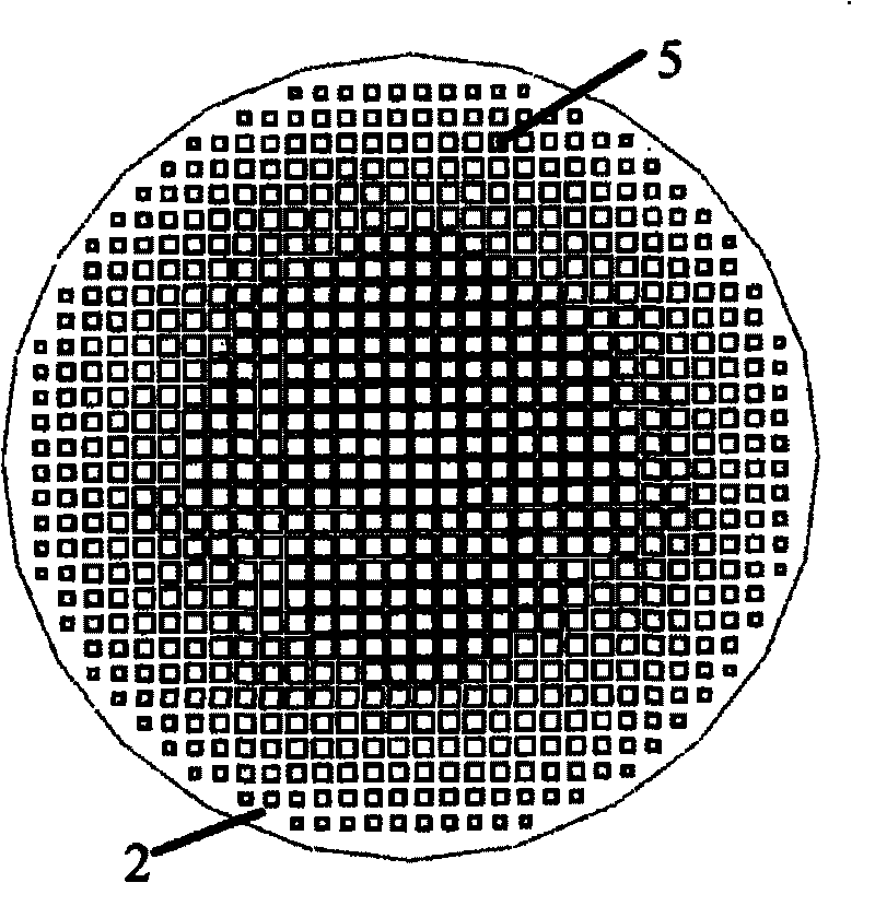
[0030] Such as image 3 and Figure 4 As shown, the core board 2 contains several non-resonant basic units of the core board. The non-resonant basic unit of the core board can be located on the plane of the core board 2 away from the feed source, or on the plane of the core board 2 close to the feed source, or on two planes of the core board 2 at the same tim...


PUM


Abstract

The invention relates to a lens antenna which comprises a metal loudspeaker (4) and a lens (1), wherein the metal loudspeaker (4) is provided with a feed source; the feed source is embedded in the smaller-diameter end of the metal loudspeaker (4), and the lens (1) is embedded in the larger-diameter end of the metal loudspeaker (4); the lens (1) comprises a core plate (2); the core plate (2) is a planar dielectric plate, and one of the planes is provided with a plurality of core-plate disresonance basic units; a core-plate metal square frame (5) is printed in each core-plate disresonance basicunit; and the areas of the core-plate disresonance basic units and the core-plate metal square frames (5) gradually decrease from the center to the edge of the core plate (2). As the core plate (2) is planar, the lens (1) is easy to manufacture. In addition, the lens (1) also comprises matching plates (3) positioned on both sides of the core plate (2). The matching plates (3) can reduce the reflection of the electromagnetic waves on the interface of the lens (1) and the air.

Description

technical field [0001] The invention relates to a lens antenna, which is used in communication systems such as microwave relay communication and satellite communication to receive and send information. Background technique [0002] At present, the lenses in commonly used lens antennas all have curved surfaces. For example, the application number is 97104401.5, the patent document titled lens antenna for improving dielectric lens to reduce internal reflected wave interference, discloses a lens antenna, comprising a conical radiator and a lens mounted on the opening of the radiator, the lens On the first side there is a planar surface facing free space, and on the second side opposite to the first side there is a hyperboloid of revolution. The application number is 200710140739.2, and the patent document named a radio wave lens antenna device discloses a lens antenna, which includes a hemispherical Lunberg lens formed by a dielectric, a hemispherical section of the ball of th...

Claims


Application Information

Patent Timeline
IPC IPC(8): H01Q15/08H01Q19/06
Inventor 崔铁军陈曦马慧锋杨歆汨程强
Owner SOUTHEAST UNIV
Why Eureka
Try Eureka