
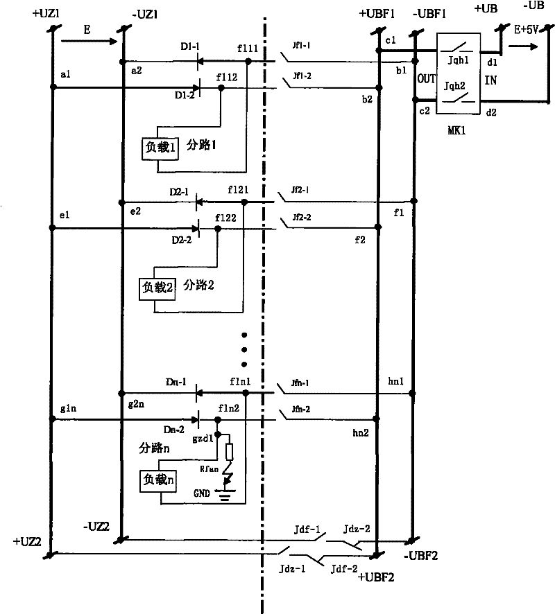
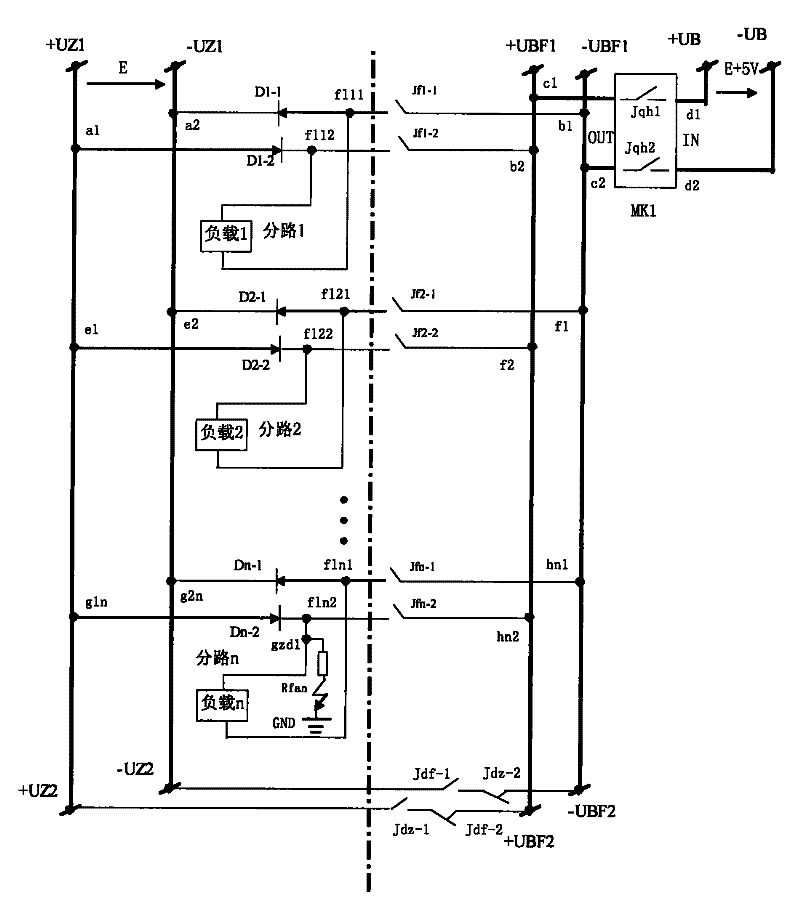
Isolation circuit structure of one pole grounding fault of branch power supply of main DC system

A technology of DC system and DC power supply, applied in circuit devices, emergency power supply arrangement, information technology support system, etc., can solve the problems of high accident probability, large measurement error, high multi-point grounding, etc., and achieve structural safety and no electromagnetic pollution Effect

Active Publication Date: 2011-12-07
WUXI POWER SUPPLY JIANGSU PROVINCE ELECTRIC POWER +1
View PDF1 Cites 0 Cited by
  • Summary
  • Abstract
  • Description
  • Claims
  • Application Information

AI Technical Summary

Problems solved by technology

[0002] At present, in the known DC system insulation monitoring devices, there are AC method and DC pulse method for insulation monitoring and finding ground faults. The function of the insulation monitoring device cannot completely isolate a certain branch circuit for measurement, resulting in problems such as too large measurement error, and by The power system accidents caused by this also happen from time to time.
After analysis, there are mainly the following problems: 1. The insulation of the DC system has dropped in a large area, and it is difficult for the current device to find the fault point when multiple points are grounded at the same time.
For example, two or more points of the same polarity in different circuits are grounded at multiple points, and two or more points in different circuits with different polarities are grounded at multiple points. It is difficult to find the fault point.
Because the device does not automatically find the fault point, the accident probability of causing a power outage in the whole station is relatively high when manually searching for the operation
2. At present, the device basically alarms when the grounding resistance is ≤15KΩ to below 7KΩ, but according to the requirements of "Technical Regulations for DC System Design of Substations in Thermal Power Plants" (DL / 5044-95) (insulation resistance ≥100KΩ)
The disadvantages of the AC method are: 3.1 The DC system has many anti-interference capacitors, and the capacitance is very large, which greatly diverts the AC test signal
3.2 But the load has inductance such as a relay, and the relay coil has resistance. In fact, the inductance, capacitance, and resistance will resonate with the AC signal, and there will be an equivalent reactance and equivalent resistance. The equivalent reactance can be eliminated by the phase-locking method. , but the equivalent resistance cannot be eliminated by the phase-locking method
Because the equivalent grounding resistance and the grounding resistance are in the same phase, there is no phase difference, and phase-locking and phase-detection techniques are useless to it
4. In the future, the DC systems of power plants and substations will become larger and more complex, the anti-interference capacitance will become larger and larger, the requirements for the DC monitoring system will be higher and higher, and the measurement error of the AC method will be greater. The probability of multiple grounding will be higher
The common disadvantage of all previous methods is that each branch circuit cannot be completely isolated from the main DC system
5. Adding measuring alternating current to direct current will cause electromagnetic pollution, which does not meet the requirements of regulations
6. Although the DC pulse method has no electromagnetic pollution, it is a method of checking waveforms with standard images and fault images. Due to the ever-changing on-site conditions, there are many undeterminable factors in the comprehensively analyzed images, and its accuracy and sensitivity are even worse.
[0006] To solve the problem of fault finding in various grounding situations: 1. Single-point grounding, 2. Two-point grounding with two poles in the same circuit, 3. Two-point grounding with the same pole in different circuits, 4. Two-point grounding in different circuits with different poles, 5. Different Three-point grounding for different poles of the circuit, 6. Multiple points for different poles of different circuits: four-point grounding and above

Method used


Image

  • Isolation circuit structure of one pole grounding fault of branch power supply of main DC system
  • Isolation circuit structure of one pole grounding fault of branch power supply of main DC system

Examples


Embodiment Construction

[0017] The present invention will be further described below in conjunction with drawings and embodiments. The following main and backup DC power supplies are referred to as main and backup power supplies.

[0018] The invention utilizes the standby power supply to completely isolate the grounding fault of one pole of each branch circuit power supply of the main direct current system in time-sharing, so as to monitor the insulation resistance of each branch circuit to the ground and implement a circuit structure with an isolation function. Specifically, a shunt relay is used to control the main and backup power supplies to operate in parallel through diodes. Whoever has the higher voltage supplies power. During measurement, the backup power supply is 5V higher than the main power supply. A diode paralleled to the positive poles of the main and standby power supplies is short-circuited, and a diode paralleled to the negative poles of the main and standby power supplies is natur...


PUM


Abstract

The invention relates to a circuit structure for isolating a one-pole ground fault of a branch power supply of a main DC system. The circuit structure adopts a shunt relay to make diodes of shunted main power supply and stand-by power supply operated in parallel so as to ensure the reliability of the power supplies; the circuit structure utilizes that the stand-by power supply is 5V higher than the main power supply and a positive or negative-pole short-circuit relay contact cuts off positive or negative-pole parallel diodes so as to force negative or positive-pole parallel diodes in the nth loop of a point to cut off; and the circuit structure thoroughly isolates the one-pole ground fault of each branch power supply of the main DC system in a time sharing way so as to have the isolation function of monitoring ground insulation resistance of each branch loop. The circuit structure has the advantages of laying a foundation for measuring the ground insulation resistance of each branch loop with high sensitivity and high precision so as to achieve the effect of comprehensively monitoring insulation of the DC system on line by using a full DC method.

Description

technical field [0001] The invention relates to a circuit structure for isolating a fault in a power supply system, in particular to a circuit structure for isolating a grounding fault of one pole of a branch power supply of a main DC system. Background technique [0002] At present, in the known DC system insulation monitoring devices, there are AC method and DC pulse method for insulation monitoring and finding ground faults. The function of the insulation monitoring device cannot completely isolate a certain branch circuit for measurement, resulting in problems such as too large measurement error, and by The power system accidents caused by this also happen from time to time. After analysis, there are mainly the following problems: 1. The insulation of the DC system has dropped in a large area, and it is difficult for the current device to find the fault point when multiple points are grounded at the same time. For example, if two or more points of the same polarity are ...

Claims


Application Information

Patent Timeline
Patent Type & Authority Patents(China)
IPC IPC(8): H02J9/06
CPCY02B70/30Y04S20/20
Inventor 何有钧何光华赵东升
Owner WUXI POWER SUPPLY JIANGSU PROVINCE ELECTRIC POWER
Learn More