
Steel bridge floor cracking inhibition paving structure and construction method thereof

A construction method and steel bridge deck technology, applied to bridges, bridge parts, bridge construction, etc., can solve problems such as pit damage, frequent maintenance, and low strength of the bonding layer, so as to save construction cost, reduce maintenance cost, and improve the construction process. simple effect

Active Publication Date: 2010-05-05
易志坚
View PDF0 Cites 9 Cited by
  • Summary
  • Abstract
  • Description
  • Claims
  • Application Information

AI Technical Summary

Problems solved by technology

[0005] The tensile strain on the surface of the pavement layer is too large due to the heavy load; the fatigue resistance of the pavement layer material is insufficient; the overall tensile strength of the pavement is insufficient, and it cracks obliquely when driving; the bridge structure, especially the deck system, is caused by insufficient rigidity. The pavement structure cracks due to excessive tensile strain on the surface of the pavement layer
[0006] (2) Rutting damage
[0008] (3) Delamination and shift damage
If the strength of the bonding layer is low and cannot withstand the interface stress caused by the external load, delamination will occur. If the high temperature stability of the pavement layer material is poor, it is easy to lose stability under the action of horizontal force, thus forming a shift and Embrace the disease
[0010] (4) Pothole damage
[0012]Due to the existence of the above diseases, the steel bridge deck pavement structure has a short service life and frequent maintenance, which not only greatly increases the maintenance cost of the bridge deck, but also affects the normal operation of the bridge. use

Method used


Image

  • Steel bridge floor cracking inhibition paving structure and construction method thereof
  • Steel bridge floor cracking inhibition paving structure and construction method thereof

Examples


Embodiment Construction

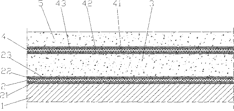
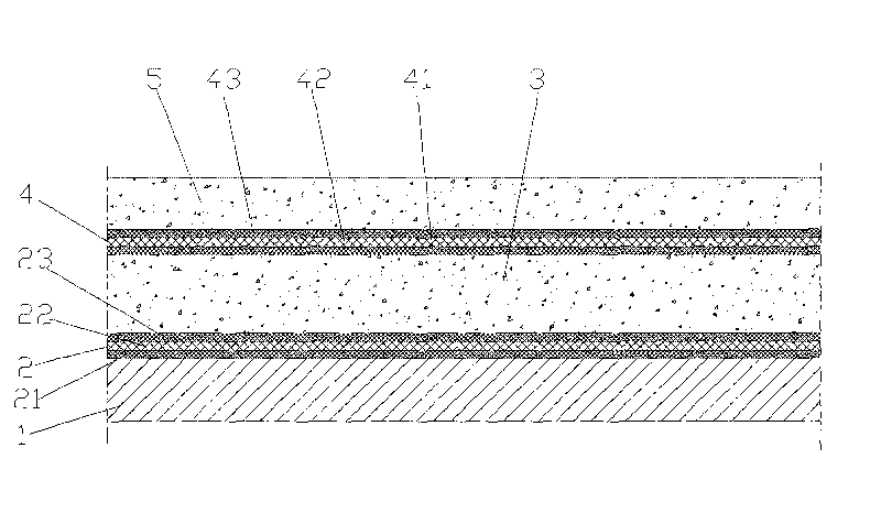
[0034] Accompanying drawing is the structure schematic diagram of the present invention, as shown in the figure: the steel bridge deck crack resistance pavement structure of the present embodiment comprises steel bridge deck 1 and bridge deck pavement structure, and described bridge deck pavement structure comprises The crack-resistant and waterproof adhesive layer I2 on the upper surface of the bridge, the crack-resistant and waterproof adhesive layer I2 is firmly combined from bottom to top, including the lower adhesive layer I21 and the crack-resistant layer I22, the lower adhesive layer The material of I 21 is a polymer, and the material of the crack resistance layer I 22 is fiber reinforced plastic (FRP).

[0035] In this embodiment, an upper adhesive layer I 23 is also provided on the crack-resistant layer I, and the material of the upper adhesive layer I 23 is a polymer; further increasing the bonding of the crack-resistant and waterproof adhesive layer I 2 Strength, im...


PUM


Abstract

The invention discloses a steel bridge floor cracking inhibition paving structure and a construction method thereof. The bridge floor paving structure comprises cracking inhibition bonding layers I, wherein the cracking inhibition bonding layers I are paved on the upper surface of a steel bridge floor; the cracking inhibition bonding layers I are firmly combined in sequence from bottom to top and comprise a lower bonding layer I and a cracking inhibition layer I; the lower bonding layer I is made of polymers, and the cracking inhibition layer I is made of fiber reinforced plastics with functions of cracking inhibition strengthening and water prevention. The invention enables the bridge surface paving structure to be firmly bonded with the steel bridge floor, ensures the deformation stress coordination of the steel bridge floor and the bridge floor paving structure and the use performance of bridges, has the functions of water and rust prevention and cracking prevention and resistance and the effect of strengthening the steel bridge floor, greatly prolongs the service life of the bridge floor paving structure and the steel bridge floor, reduces the maintenance cost, and can be finished by simple operation of coating, maintenance, cold mixture and pavement; and a bridge surface paving layer has simple construction process and is economic and durable.

Description

technical field [0001] The invention belongs to the field of building structures and road engineering, in particular to a steel bridge deck crack-resistant pavement structure and a construction method. Background technique [0002] The bridge deck pavement is one of the important components of the bridge structure. It not only directly bears the pressure, impact and shear load of the vehicle load, but also is worn and weathered by the vehicle and the climate environment, and also plays a role in protecting the main body of the bridge and To provide safe and comfortable road surface functions for driving, therefore, steel bridge deck pavement has been highly valued and concerned by domestic and foreign academic circles and engineering circles, but bridge deck pavement, especially steel bridge deck pavement, is still a worldwide phenomenon. problem. [0003] The bridge deck pavement structure presents a variety of characteristics according to different design ideas and use en...

Claims


Application Information

Patent Timeline
IPC IPC(8): E01D19/12
Inventor 易志坚赵朝华杨庆国马银华何小兵黄锋谷建义
Owner 易志坚
Learn More