Deicer for high-voltage power transmission line and deicing method thereof

A technology of high-voltage transmission lines and high-voltage transmission lines, which is applied in the installation of cables, electrolytic components, electrical components, etc., can solve the problems of unable to prevent the formation of ice coating, damage of power facilities, disconnection of transmission lines, etc., and achieve significant economic benefits and social value, low maintenance and low cost

Inactive Publication Date: 2010-05-12
NORTHEAST DIANLI UNIVERSITY
View PDF0 Cites 35 Cited by
  • Summary
  • Abstract
  • Description
  • Claims
  • Application Information

AI Technical Summary

Problems solved by technology

[0002] In January 2008, most parts of Central China, East China, and South China experienced low-temperature, rainy, snowy and freezing weather that was rare in history, causing large areas of power transmission and transformation facilities to be covered with ice. A la...

Method used


Image

  • Deicer for high-voltage power transmission line and deicing method thereof
  • Deicer for high-voltage power transmission line and deicing method thereof
  • Deicer for high-voltage power transmission line and deicing method thereof

Examples


Embodiment 1

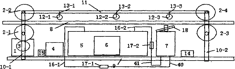
[0041] from figure 1 Visible, a kind of high-voltage transmission line deicing device of the present invention, it is connected and fixed by supporting plate 9 and the fixed support I, II (10-1, 10-2) on it with crossbeam 11, is on the high-voltage transmission line 8 , the lower and the tension wheel I 2-1, II 2-2 and the tension wheel III 2-3, IV 2-4 connected to the top and middle part of the fixed bracket I10-1, II 10-2 respectively, and The drive motor 1 drives the aforementioned tension wheel I 2-1, II 2-1 and tension wheel III 2-3, IV 2-4 to rotate through the gear 3 installed on the fixed bracket I 10-1. The trolley walking on the line 8, and a sensor for detecting the degree of inclination is installed on it to realize the steering movement of the trolley close to the iron tower; and it is located at the lower part of the high-voltage transmission line 8, between the fixed brackets I 10-1 and II 10-2 On the described pallet 9, accumulator 4, electrolytic cell 5, sola...

Embodiment 2

[0045] A method for deicing a high-voltage transmission line, which is located on the supporting plate 9 on the trolley on the high-voltage transmission line 8, and the strong electrolyte sulfuric acid or sodium hydroxide solution accounting for 1 / 2 of its total volume is housed in the fixed electrolytic cell 5, Its concentration is 15wt%; in the electromagnetic induction coils I 12-1, II 12-2, III suspended on the beam 11 by the suspension wires I 13-1, II 13-2, III 13-3 from the solar panel 12-3 Electromagnetic induction electric energy generated under wind force or motion, and boosted by high voltage ( Figure 5 ), voltage doubler rectifier ( Image 6 ),Regulator circuit( Figure 7 ), connect to the storage battery through the lead, continuously charge the storage battery 4, the storage battery 4 is connected to the electrolytic cell 5 through the lead, so that the oxygen and hydrogen generated by the electrolysis of sulfuric acid or sodium hydroxide solution therein pass ...


PUM


Abstract

The invention relates to a deicing method for a high-voltage power transmission line and a device. The device is located on a supporting plate of a travel carriage on the high-voltage power transmission line and fixedly provided with an electrolytic cell filled with strong electrolyte solution and the like. The storage battery is charged continuously through electromagnetic inducing electrical energy which is from a solar cell panel and is generated under wind power or movement of three electromagnetic induction coils that are suspended on a beam and from a solar cell plate. The storage battery is connected with the electrolytic cell. Hydrogen and oxygen generated by the electrolytic cell enter a combuster through a delivery pipe, a one-way valve, a polycarbonate pipe and a lock net adaptor, respectively; a spring sheet metal and a thin plate that form an ice and snow detector as well as an electrode connected with a power line of a high-voltage boosting circuit below the reed pipe are arranged at the top of the combuster below the high-voltage transmission line. When the thin plate is covered by ice, and elastic metal and thin plate bend downwards, the free end and the magnetic block at the top of the combuster attract each other, and the power line of a high-voltage boosting circuit is switched on. Mixture of hydrogen and oxygen in the combuster combusts so that the piston body in the combuster strikes the high-voltage transmission line to enable the ice and snow to fall off.

Description

technical field [0001] The invention relates to a high-voltage transmission line deicing device and a deicing method thereof. Background technique [0002] In January 2008, most parts of Central China, East China, and South China experienced historically rare low-temperature, rainy, snowy and freezing weather, causing large areas of power transmission and transformation facilities to be covered with ice. A large number of transmission lines were disconnected, power facilities were extensively damaged, and the grid structure was severely damaged. [0003] From 1980 to 2007, the total investment in power supply in China reached 2,109.7 billion yuan, and the installed capacity and power generation have leapt to the second place in the world. , A new stage of long-distance power transmission. However, this huge system was so fragile in the face of this sudden ice and snow disaster that it was unbearable to deal with: hundreds of thousands of poles and towers collapsed, several...

Claims


Application Information

Patent Timeline
IPC IPC(8): H02G7/16C25B1/02
CPCY02P20/133
Inventor 高经伍高原何召慧
Owner NORTHEAST DIANLI UNIVERSITY
Why Eureka
Try Eureka