
Sliding block unidirectional control device of automobile energy-saving sliding device

A technology of one-way control and sliding device, which is applied in control devices, vehicle parts, transportation and packaging, etc. It can solve the problems of large contact area between pawl and ratchet, difficult processing of pawl and ratchet, easy wear and heat, etc. Achieve the effect of good car inertial energy, avoid anti-drag engine, and large bearing capacity

Inactive Publication Date: 2010-05-19
陈巧青 +2
View PDF1 Cites 2 Cited by
  • Summary
  • Abstract
  • Description
  • Claims
  • Application Information

AI Technical Summary

Problems solved by technology

However, the one-way control device for energy-saving sliding in the above-mentioned patent adopts a pawl and a ratchet as a circumferential cooperation structure, which is not only difficult to process the pawl and the ratchet, but also has high processing and manufacturing costs; moreover, the contact area between the pawl and the ratchet is large. , easy to wear and generate heat during use, and the service life is short

Method used


Image

  • Sliding block unidirectional control device of automobile energy-saving sliding device
  • Sliding block unidirectional control device of automobile energy-saving sliding device
  • Sliding block unidirectional control device of automobile energy-saving sliding device

Examples


Embodiment 1

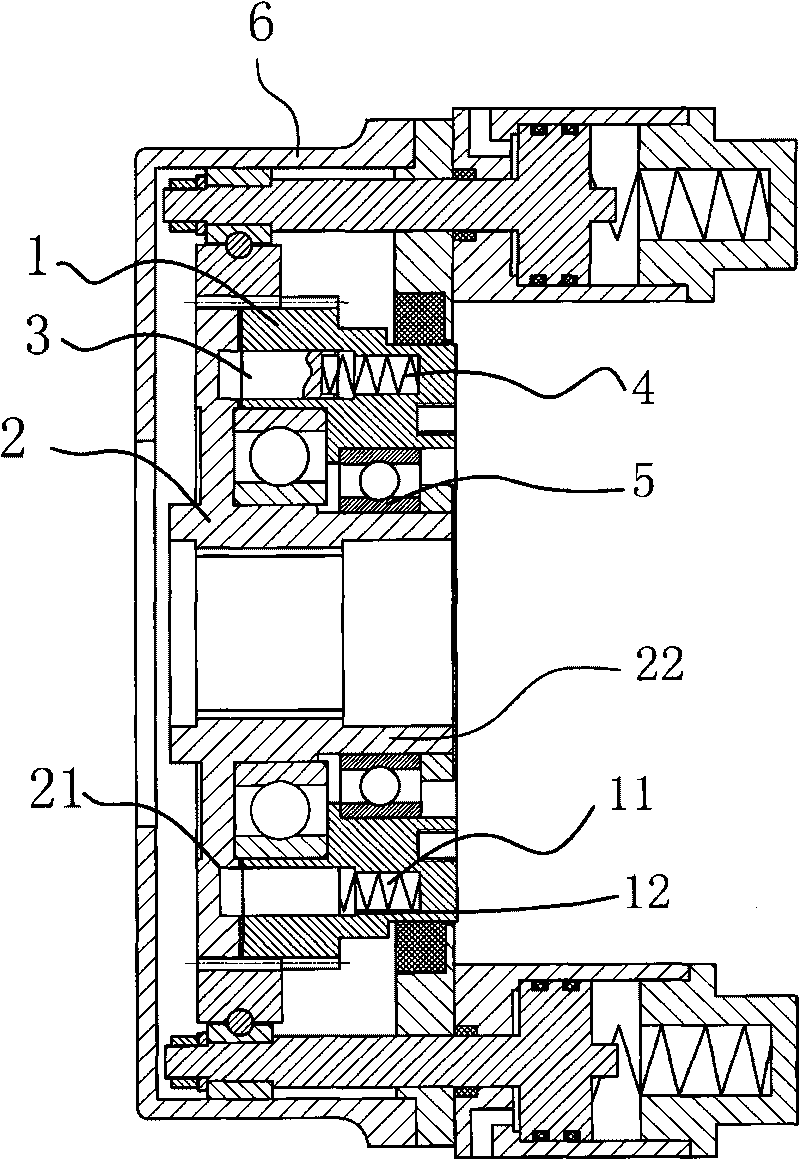
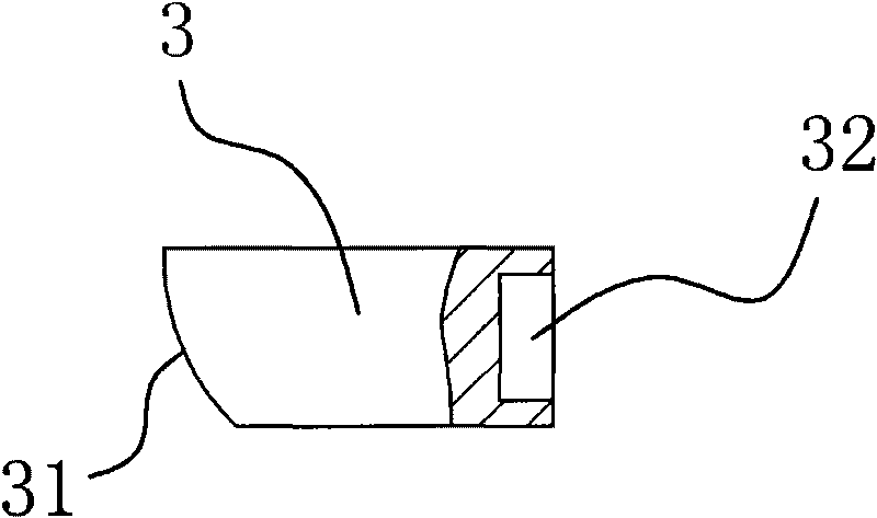
[0027] Such as figure 1 with figure 2 As shown, the slider-type one-way control device of the automobile energy-saving sliding device of the present invention is arranged in the housing 6 of the automobile energy-saving sliding device, and includes a transmission disc 1, an output disc 2, two bearings 5 ​​and an overrunning clutch mechanism.

[0028] The drive disc 1 and the output turntable 2 are both disc-shaped and have outer circumferences of the same diameter. The drive plate 1 is provided with a through hole coaxially arranged with the drive plate 1. There are eight counterbore holes 11 on the end surface of the drive plate 1. The counterbore 11 is a stepped hole, and the counterbore 11 has a step 12, The eight counterbores 11 are evenly distributed on the end surface of the drive disc 1 along the same circumference. The output turntable 2 is provided with spline holes, and the end surface of the output turntable 2 is provided with ratchet grooves 21 that are an integer mu...

Embodiment 2

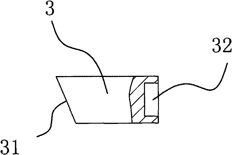
[0033] Such as image 3 As shown, the slider-type one-way control device of the automobile energy-saving sliding device of the present invention has a structure and function similar to that of Embodiment 1, wherein the inclined surface 31 on the slider pawl 3 is an inclined plane.


PUM


Abstract

The invention provides a sliding block unidirectional control device for an automobile energy-saving sliding device, belongs to the technical field of automobile, and solves the problems of high processing cost, easy abrasion and heat generation of the conventional unidirectional control device. The sliding block unidirectional control device for the automobile energy-saving sliding device comprises a disc-shaped driving disc and an output turntable. The driving disc and the output turntable are coaxially arranged. An overrunning clutch mechanism which can make the driving disc drive the output turntable to rotate together is arranged between the driving disc and the output turntable. When a rotating speed of the output turntable is higher than that of the driving disc, the output turntable can rotate freely relatively to the driving disc. The overrunning clutch mechanism in the invention adopts an axial matching structure of a sliding block pawl, a spring and a ratchet groove, not only has simple structure and convenient processing and installation and can better utilize inertial energy of the automobile and avoid driving an engine reversely, but also has the characteristics of large bearing capacity, small contact area and difficult heat generation, and can effectively prolong the service life of the automobile energy-saving sliding device.

Description

Technical field [0001] The invention belongs to the technical field of automobiles, and relates to an automobile energy-saving sliding device, in particular to a sliding block type one-way control device of the automobile energy-saving sliding device. Background technique [0002] There will be frequent speed changes in the driving process of a car, often accompanied by acceleration, deceleration and coasting. Sometimes the engine drives the vehicle, and sometimes it is the inertial reverse drive engine of the car. These changes cannot be grasped and controlled by the driver at any time, so The inertial energy in the driving process of the car is wasted through the transmission shaft to the engine when the engine generates reverse drag. This causes the loss of inertial energy and the increase in fuel consumption, and at the same time increases the environmental impact of exhaust gas during the driving process. Pollution. [0003] In order to make full use of the inertial energy of...

Claims


Application Information

Patent Timeline
Patent Type & Authority Applications(China)
IPC IPC(8): B60K17/26
Inventor 陈巧青施建国徐君义
Owner 陈巧青
Features
  • Generate Ideas
  • Intellectual Property
  • Life Sciences
  • Materials
  • Tech Scout
  • Unparalleled Data Quality
  • Higher Quality Content
  • 60% Fewer Hallucinations
Learn More