Graphite heat radiator
A heat dissipation device, graphite technology, applied in the direction of cooling/ventilation/heating transformation, electrical components, electric solid devices, etc., can solve the problem that the graphite sheet material cannot be fixedly connected to the metal base, achieve good heat dissipation effect, simple structure, and heat conduction good performance
- Summary
- Abstract
- Description
- Claims
- Application Information
AI Technical Summary
Problems solved by technology
Method used
Image
Examples
Embodiment 1
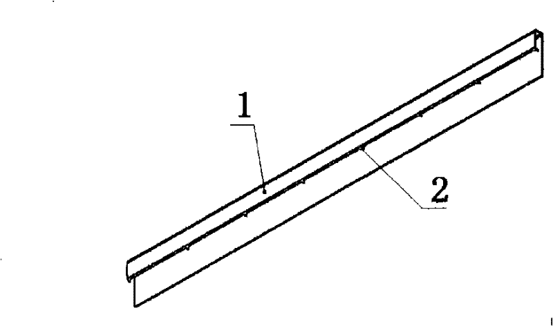
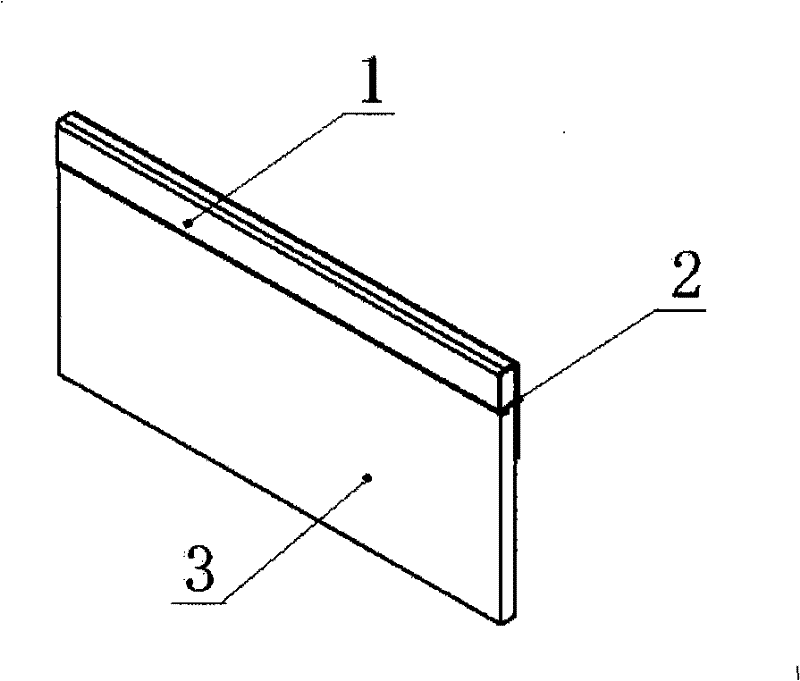
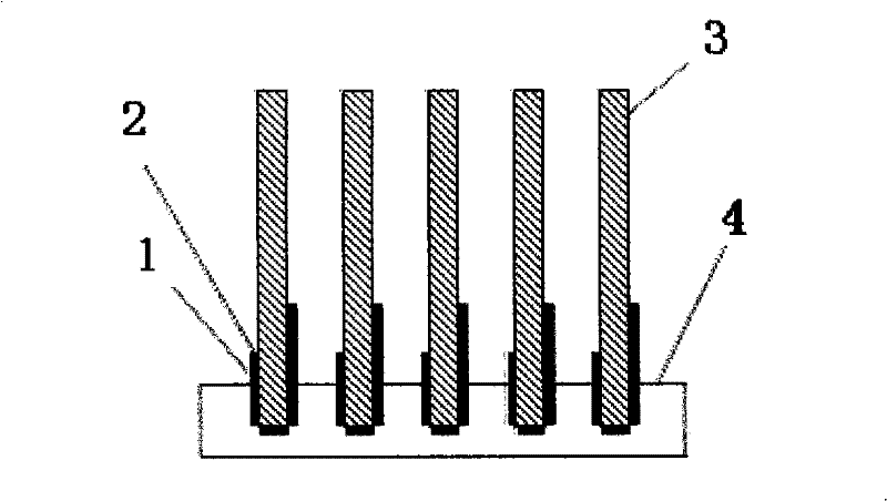
[0037] The structure of the graphite cooling device of this embodiment is as attached figure 1 , attached figure 2 , attached image 3 , attached Figure 4 shown.
[0038] in the attached figure 1 , attached figure 2 Among them, the sheet metal connector 1 connected to the graphite sheet is made of high thermal conductivity metal, preferably copper or aluminum sheet, and the edge of the shorter end edge of the sheet metal connector 1 has several grooves made inward. Puncture tenon 2. Use the metal edge wrapping machine to bend and wrap the metal sheet, so that the metal sheet is bent into a U-shaped opening groove along one side of the graphite sheet, and the width of the opening is slightly wider than the width of the seal to ensure smooth insertion of the graphite sheet . The graphite sheet 3 is inserted into the metal sheet bent into a groove-shaped edge-wrapping groove, and then press-fitted so that the puncture tenon 2 is inserted into the graphite sheet, and the...
Embodiment 2
[0043] The structure of the graphite cooling device of this embodiment is as attached Figure 5 , attached Figure 6 , attached Figure 7 , attached Figure 8 shown.
[0044] in the attached Figure 5 And attached Figure 6 Among them, the metal connector is in the shape of a rivet, and the rivet-shaped metal connector 5 is made of high thermal conductivity metal such as copper and aluminum. The shape metal connector 5 is fixed with the graphite sheet, and the metal sheet 8 is positioned between the rivet cap and the graphite sheet. The graphite sheet is punched with the same mounting holes as the number of the metal sheets, and one end of the metal sheet stretches into the mounting holes. Graphite fins with metal flakes are formed. In this way, graphite sheets are fixed layer by layer to form graphite fin groups. Then one end of the metal sheet is fixed in the groove directly contacting the metal base 9 of the heat source, so that the metal sheet 8 transfers the heat o...
Embodiment 3
[0046] The structure of the graphite cooling device of this embodiment is as attached Figure 9 , attached Figure 10 , attached Figure 11 , attached Figure 12 shown.
[0047] in the attached Figure 10 And attached Figure 11 Among them, the columnar metal connector 10 is made of high thermal conductivity metal materials such as copper and aluminum, and four vertical clamping lines are made on the side of the columnar metal connector 10. The tenon 11 fixes the graphite sheet; the graphite sheet 14 is cut to a corresponding size, and a hole is opened in the middle of the graphite sheet. The sides have the same size, and the two sides of the graphite sheet 14 are perforated according to the size of the bottom area of the heat pipe, and the specific number of graphite sheets is determined according to the shape and needs of the heat pipe. Graphite sheets 14 arrange and fix each graphite sheet 14 at a certain distance through the tenon or puncture tenon 11 on the column...
PUM
| Property | Measurement | Unit |
|---|---|---|
| thickness | aaaaa | aaaaa |
Abstract
Description
Claims
Application Information
 - R&D
- Intellectual Property
- Life Sciences
- Materials
- Tech Scout
- Unparalleled Data Quality
- Higher Quality Content
- 60% Fewer Hallucinations
Browse by: Latest US Patents, China's latest patents, Technical Efficacy Thesaurus, Application Domain, Technology Topic, Popular Technical Reports.
© 2025 PatSnap. All rights reserved.Legal|Privacy policy|Modern Slavery Act Transparency Statement|Sitemap|About US| Contact US: help@patsnap.com


