Supercharge Your Innovation With Domain-Expert AI Agents!

Centrifugal scraping plate film formation pyrolysis reaction device and method thereof

A thermal cracking and scraper technology, which is used in non-catalytic thermal cracking, cracking, preparation of liquid hydrocarbon mixtures, etc., can solve the problems of long reaction period, slow heat transfer of grooved rotary cracking reactor, secondary pollution, etc. The superiority of performance is outstanding, overcoming the effect of long reaction period and strong adaptability

Inactive Publication Date: 2010-05-26
徐效奇 +1
View PDF0 Cites 13 Cited by
  • Summary
  • Abstract
  • Description
  • Claims
  • Application Information

AI Technical Summary

Problems solved by technology

[0006] The trough-type rotary cracking reactor has slow heat transfer, long reaction cycle, incomplete cracking reaction, serious carbonization, and the end product is sticky coke that is difficult to handle, and the secondary pollution is serious, especially for the treatment of waste plastics.
[0007] The disadvantage of the method of using the above-mentioned cracking reactor to realize the cracking reaction is that the reaction period is long, the cracking reaction is incomplete, carbon formation is serious, and the end product is viscous coke, which is difficult to clean up and causes secondary pollution, especially for waste plastics. It is more obvious when harmless treatment

Method used


Image

  • Centrifugal scraping plate film formation pyrolysis reaction device and method thereof
  • Centrifugal scraping plate film formation pyrolysis reaction device and method thereof
  • Centrifugal scraping plate film formation pyrolysis reaction device and method thereof

Examples


Embodiment Construction

[0023] The present invention will be further described below in conjunction with the accompanying drawings and embodiments.

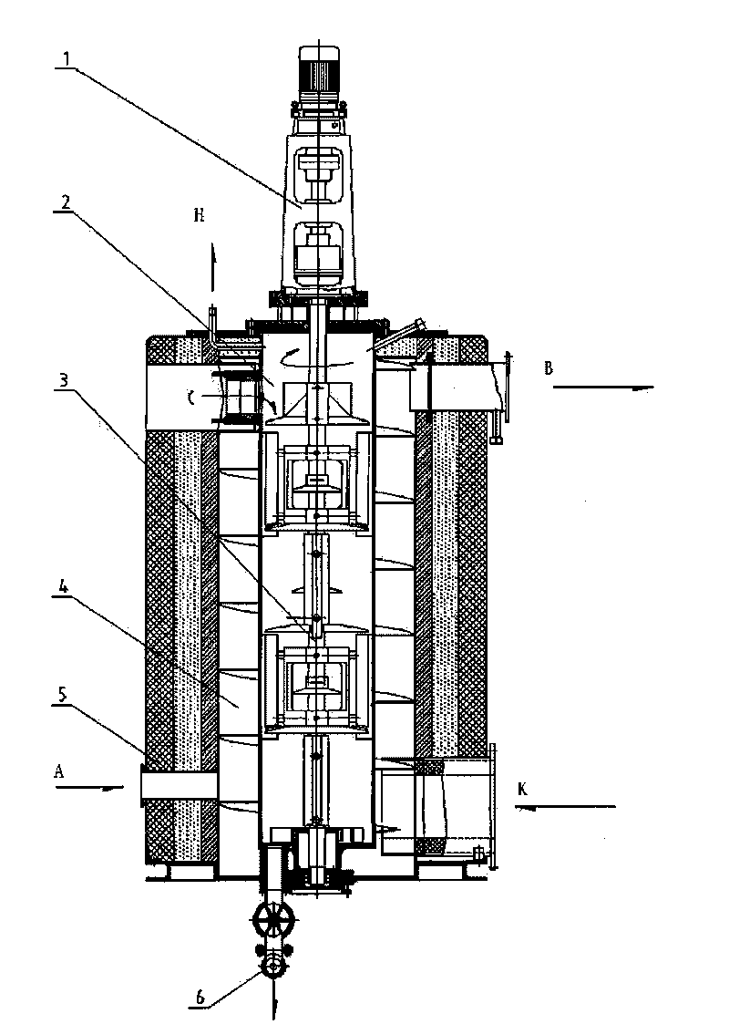
[0024] Such as figure 1 As shown, the centrifugal scraper film-forming pyrolysis reaction device of the present invention includes a furnace body 2, a scraper assembly 3 driven by a reducer 1, a spiral flue 4, a heat preservation cover 5, and a gas-blocking discharge device 6.

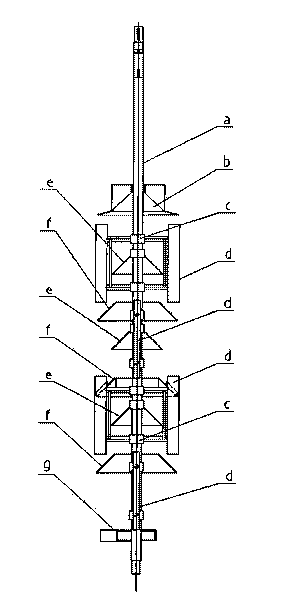
[0025] Such as figure 2 As shown, the scraper assembly 3 is composed of a primary distribution plate b, multiple sets of scrapers d, a scraper frame c, a baffle plate e, a secondary distribution plate f, a discharge plate g and a main shaft a, which is that the main shaft a From top to bottom, the primary distribution plate b, the scraper frame c, the material retaining plate e, the secondary distribution plate f, the material retaining plate e, the secondary distribution plate f, the scraper frame c, the material retaining plate e, The secondary distribution plate f, the dis...


PUM


Abstract

The invention discloses centrifugal scraping plate film formation pyrolysis reaction device and method thereof. The device comprises a furnace body, a scraping plate assembly driven by a speed reducer, a spiral flue, a heat preservation cover and an air-resistance discharging device. The furnace body is divided into three intervals including a low-temperature reaction area, a high-temperature reaction area and a carbonization area from top to bottom; the scraping plate assembly comprises a primary distribution disc fixed on a principal axis, a plurality of scraping plates, a scraping plate frame, a stopping plate, a secondary distribution disc and a discharging plate, wherein the scraping plates are hung on a sliding axis of the scraping plate frame. In the method, due to centrifugal forces generated by rotation, the hung scraping plates cling close to the cylinder wall of the furnace and scrape materials flowing downward along the cylinder wall into thin films, the thin films contact with the high-temperature cylinder wall to generate pyrolysis instantly. The invention has the advantages of strong adaptability, complete pyrolysis on polymers of gas oil, oil sludge, waste plastics and the like, no discharging of coke residues of ropy oily matters and wax matters during the pyrolysis, no carbonization inside equipment, rapid heat transfer, dry final product of carbon black powder, and no secondary pollution.

Description

technical field [0001] The present invention relates to a pyrolysis reaction device and its method, in particular to a thermal cracking reaction device for film formation with a centrifugal scraper and a method for using the device to scrape the reaction material into a thin film by the scraper under the action of centrifugal force, and then carry out the thermal cracking reaction instantaneously . Background technique [0002] At present, the pyrolysis reactors at home and abroad include shell and tube pyrolysis reactors, fluidized bed pyrolysis reactors, fluidized catalytic cracking units (FCC units), and tank-type rotary pyrolysis reactors for thermal cracking of waste plastics. Although the structures of these cracking reactors are different, the state of the material in the cracking process is fluid or droplet, so it has the following disadvantages: [0003] The tubular pyrolysis reactor has poor adaptability, especially when dealing with waste plastics such as waste p...

Claims


Application Information

Patent Timeline
IPC IPC(8): C08J11/12C10G9/00
CPCC10G1/10C08J11/12C10G9/00Y02W30/62
Inventor 姜林发
Owner 徐效奇
Features
  • R&D
  • Intellectual Property
  • Life Sciences
  • Materials
  • Tech Scout
  • Unparalleled Data Quality
  • Higher Quality Content
  • 60% Fewer Hallucinations
Learn More