Multiplier and power factor correction controller with same

A multiplier, the eleventh technology, applied in multiplication/division calculation operations, output power conversion devices, sustainable manufacturing/processing, etc., can solve the problems of THD deterioration, increase in crossover distortion, etc. Small, the effect of reducing the output power

Active Publication Date: 2013-09-04
BCD (SHANGHAI) MICRO ELECTRONICS LTD
View PDF2 Cites 0 Cited by
  • Summary
  • Abstract
  • Description
  • Claims
  • Application Information

AI Technical Summary

Problems solved by technology

Therefore, at high input voltage, the THD of the system will deteriorate due to the increase of crossover distortion
[0007] Therefore, a circuit is needed to compensate for the increase in crossover distortion when the AC input voltage is high

Method used


Image

  • Multiplier and power factor correction controller with same
  • Multiplier and power factor correction controller with same
  • Multiplier and power factor correction controller with same

Examples


Embodiment Construction

[0027] In the following, preferred embodiments according to the present invention will be described in detail with reference to the accompanying drawings.

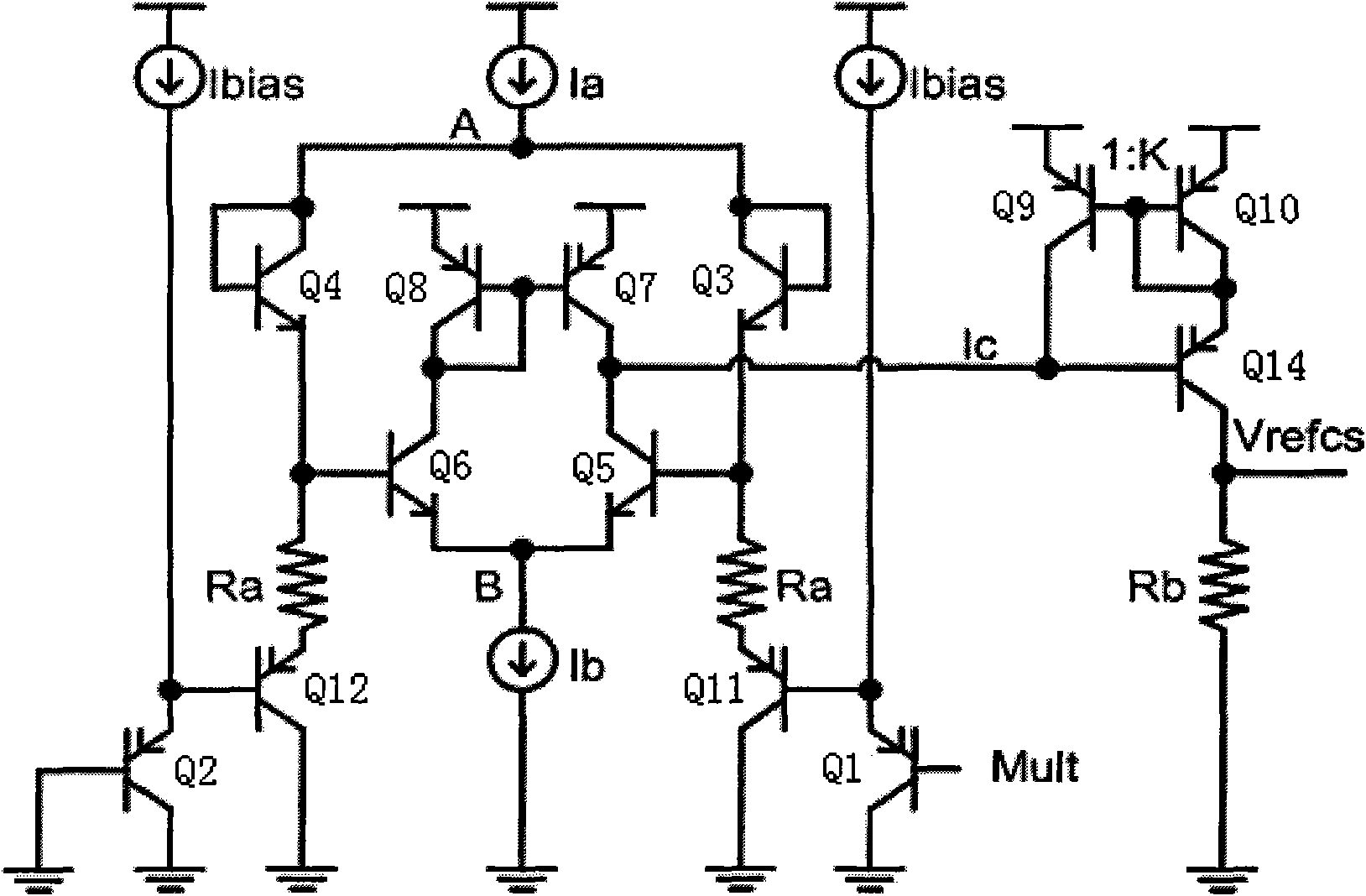
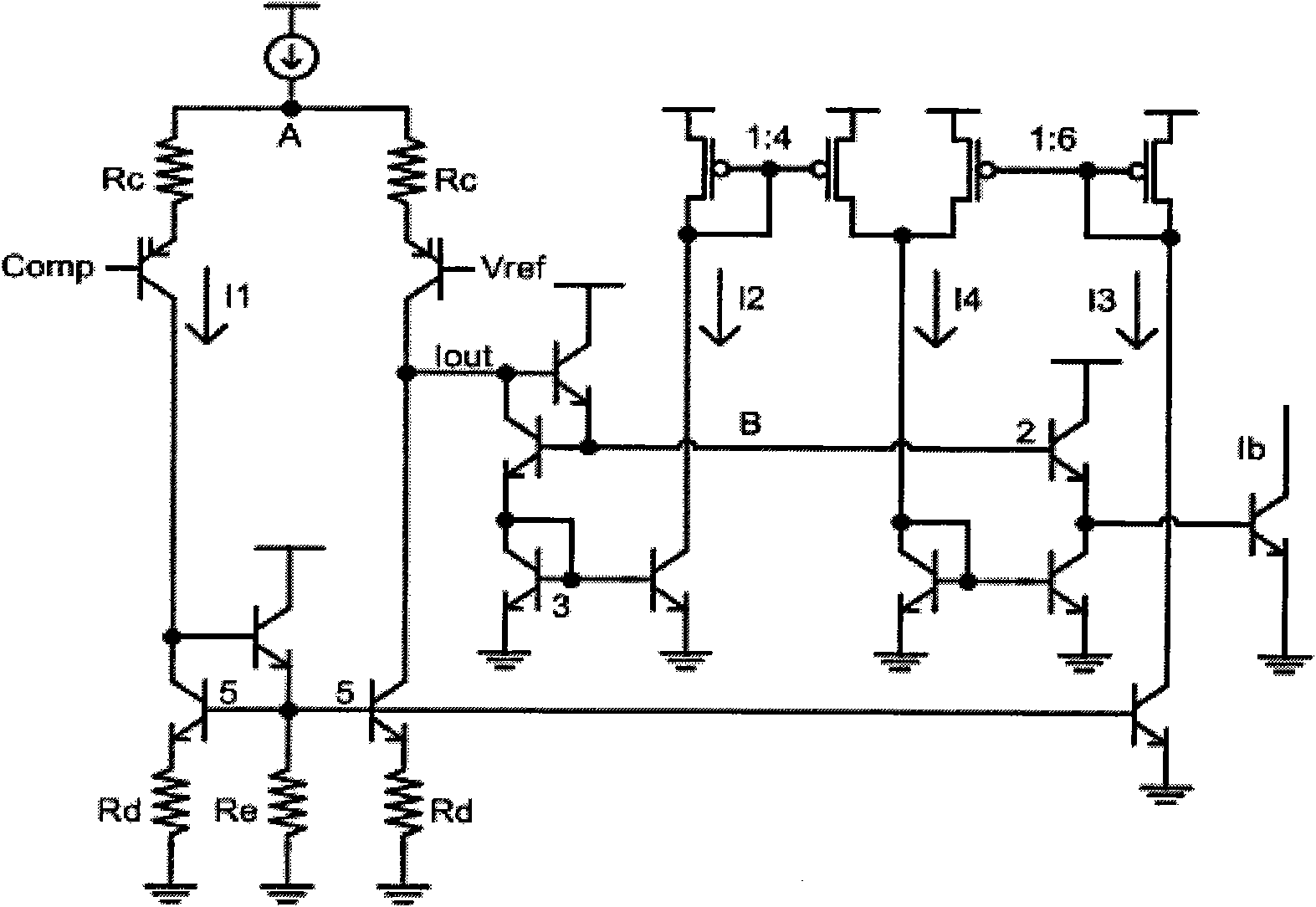
[0028] figure 2 shows the existing multiplier circuit, image 3 is used for figure 2 Shown is the bias current generation circuit for the multiplier.

[0029] refer to figure 2 , because: V beN3 +V beN1 =V beN4 +V beN2

[0030] so,

[0031] I 1 + I 2 I 1 - I 2 = I 3 + I 4 I 3 - I 4 ...


PUM


Abstract

The invention discloses a multiplier and a power factor correction controller with the same. The multiplier comprises a first differential input level, a second differential input level and an output level, wherein the first differential input level is provided with an amplitude limiter circuit which limits the amplitude of input signals of the multiplier and comprises a first transistor Q1 and a thirteenth transistor Q13; the base of the first transistor Q1 is used as an input end for receiving input voltage signals of the multiplier; the base of the thirteenth transistor Q13 is offset at a direct current voltage Vth of a zero-temperature coefficient, namely, at an amplitude limiting voltage value; and the emitter and the collector of the first transistor Q1 are connected with the emitter and the collector of the thirteenth transistor Q13 respectively. According to the invention, the output of the multiplier with the amplitude limiter circuit is used as a reference voltage of a current sampling and comparing circuit, which can limit the amplitude of the input signals of the multiplier under the condition of not influencing the input signals of a chip and can effectively solve the problem of the total harmonic distortion of a system in high-voltage input.

Description

technical field [0001] The present invention relates to a multiplier and a power factor correction controller with the multiplier, more specifically, a multiplier with a limiting circuit and a power factor correction controller with the multiplier. Background technique [0002] The power factor correction circuit is widely used in power conversion devices, and its purpose is to make the input current of the rectifier circuit a sinusoidal waveform, so that the power factor is close to 1. [0003] figure 1 It is a typical power factor correction circuit. Such as figure 1 As shown, the circuit mainly includes Boost inductor L2, switching MOSFET, diode D2, output capacitor C7 and control chip IC1 (power factor correction controller). The control chip IC1 controls the switch MOSFET to be in a high-frequency working state, and adjusts the switch conduction duty cycle according to the input voltage and output, so that the peak value of the switch current is a sinusoidal envelope...

Claims


Application Information

Patent Timeline
Patent Type & Authority Patents(China)
IPC IPC(8): G06G7/16H02M1/42
CPCY02B70/126Y02B70/10Y02P80/10
Inventor 任雪刚朱士海赵向源徐思远陈泽强
Owner BCD (SHANGHAI) MICRO ELECTRONICS LTD
Why Eureka
Try Eureka