Bearing structure and wind power generator

A technology of bearings and rolling elements, which is applied in wind power generation, bearing assembly, wind turbines, etc., can solve the problems of large man-hours, increased heat generation, and complex structures, and achieves improved reliability and durability, simplified bearing structures, and Realize the effect of the bearing structure

Inactive Publication Date: 2010-05-26
MITSUBISHI HEAVY IND LTD
View PDF1 Cites 12 Cited by
  • Summary
  • Abstract
  • Description
  • Claims
  • Application Information

AI Technical Summary

Problems solved by technology

Therefore, it has been pointed out that there are problems such as that the structure becomes complicated due to the increase in the number of parts, and a lot of man-hours are required for manufacture.
[0015] In addition, since the surface in contact with the seal is limited to either the rotating side or the fixed side, the relative speed difference determined by the speed of the rotating side becomes large, and the amount of heat generated by friction increases
Therefore, in the bearing 10, since the temperature difference between the outer ring 11 and the inner ring 12 becomes large to increase the relative deformation caused by the temperature difference, it becomes difficult to manage the clearance and pre-set of the rolling elements 14 and the outer ring 11 and the inner ring 12. to press
[0016] Moreover, in a bearing structure such as a double-row tapered roller bearing, since there is a problem that the temperature of the lubricant increases due to the influence of the heat generated by the aforementioned friction, not only the types of lubricants that can be used are limited, but also there are There is a tendency that cooling devices and the like for cooling the lubricant whose temperature rises are required, and the scale of the auxiliary equipment required for the operation of the bearing structure is also increased.

Method used


Image

  • Bearing structure and wind power generator
  • Bearing structure and wind power generator
  • Bearing structure and wind power generator

Examples


Embodiment Construction

[0050] Next, an embodiment of a bearing structure and a wind power generator according to the present invention will be described based on the drawings.

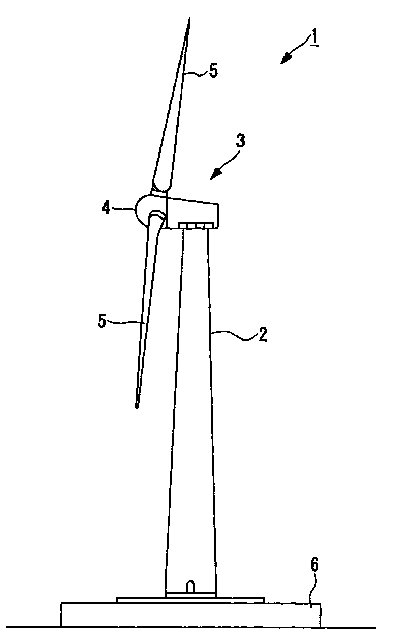
[0051] figure 2 The shown wind power generator 1 has: a pillar 2 vertically arranged on a base 6 , a nacelle 3 arranged on the upper end of the pillar 2 , and a swivel head 4 arranged on the nacelle 3 and rotatable about a substantially horizontal axis.

[0052] The rotary head 4 is provided with a plurality of blades (windmill rotary blades) 5 radially around the rotary axis. Thus, when the blades (wind turbine rotor blades) 5 receive wind force from the direction of the rotation axis of the rotation head 4, it is converted into power to rotate the rotation head 4 around the rotation axis, and the power is used to drive the power generator installed in the nacelle 3. The machine can generate electricity.

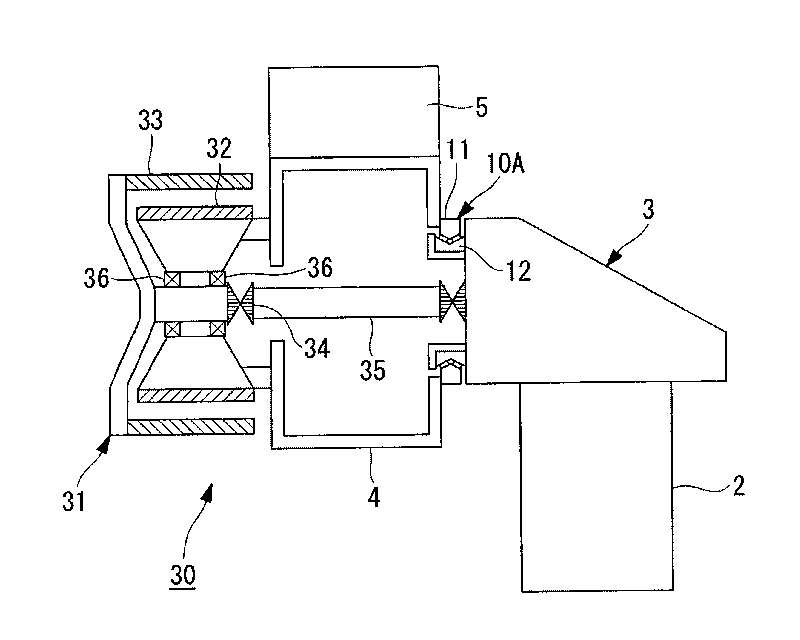
[0053] image 3 A configuration example of a power transmission system 30 installed on the swivel head side outside t...


PUM


Abstract

The invention provides a bearing structure which reduces the relative sliding speed between a seal ring (20) and contact surfaces and suppresses relative deformation due to a difference between the temperatures of inner and outer rings (11, 12). Rolling elements (14) are disposed in a space portion (16) formed between the inner ring (11) and the outer rings (12) to relatively rotate the inner ring (11) or the outer rings (12) via the rolling elements (14). The sliding portions of the surfaces of the rolling bodies (14) and the inner surface of the space portion (16) are cooled with a lubricant supplied into the space portion (16). The axial end opening of the space portion (16) is covered with the seal ring (20) attached to the retainer (13) retaining the rolling elements (14).

Description

technical field [0001] The invention relates to a bearing structure and a wind power generating device. Background technique [0002] A wind power generator is a device in which a rotating head having windmill blades is rotated by wind force, and a generator is driven by the rotational force to generate electricity. In such a wind power generator, a double-row tapered roller bearing capable of supporting torque with a single bearing or the like is used as a main bearing that supports the rotation of the rotary head. In addition, the lubricant is supplied to the sliding part so that the sliding parts such as the outer ring or the inner ring of the bearing and the rollers held between the outer ring and the inner ring operate in a sliding manner or do not generate heat. A seal member is provided in order to prevent malfunction of the sliding part due to leakage of the lubricant from the bearing, damage to the bearing due to heat generation, and the like. [0003] The sealing...

Claims


Application Information

Patent Timeline
Patent Type & Authority Applications(China)
IPC IPC(8): F16C33/78F16C19/38
CPCF16C33/7893F16C2300/14F16C2360/31Y02E10/722F16C19/381F16C19/38F16C33/4623Y02E10/728F16C2226/74Y02E10/72F03D80/70F05B2240/50
Inventor 沼尻智裕
Owner MITSUBISHI HEAVY IND LTD
Why Eureka
Try Eureka