Eureka AIR delivers breakthrough ideas for toughest innovation challenges, trusted by R&D personnel around the world.

Device for recovering oil and gas by condensation-adsorption method

A technology of recovery device and adsorption method, which is applied in the direction of distribution device, special distribution device, liquid distribution, transportation or transfer device, etc. It can solve the problems of unsatisfactory economic indicators and technical performance, affecting desorption effect, poor cooling effect, etc. Achieve high vacuum level, enhanced cooling effect, and improved life

Inactive Publication Date: 2010-06-02
江苏惠宇电仪设备有限公司
View PDF0 Cites 16 Cited by
  • Summary
  • Abstract
  • Description
  • Claims
  • Application Information

AI Technical Summary

Problems solved by technology

Condensation method and adsorption method are mainly used in oil depots, refineries and other places, but these two methods are not ideal in terms of economic indicators and technical performance.
Because the cooling effect of the vacuum pump is poor and the vacuum degree is low, it affects the desorption effect

Method used


Image

  • Device for recovering oil and gas by condensation-adsorption method
  • Device for recovering oil and gas by condensation-adsorption method
  • Device for recovering oil and gas by condensation-adsorption method

Examples


Embodiment Construction

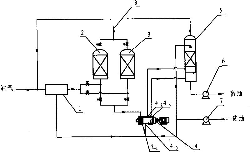
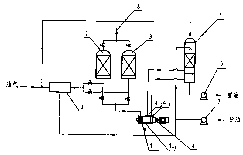
[0017] Such as figure 1 As shown, the present invention is a kind of oil gas recovery device utilizing the condensation adsorption method, the device comprises a heat exchanger 1, an adsorber 2, an adsorber 3, a dry vacuum pump 4, an absorption tower 5, a rich oil pump 6, a lean oil pump 7, The air exhaust pipe 8 is characterized in that: the left end of the heat exchanger 1 has an oil and gas inlet, and the right end has an oil and gas outlet, and the oil and gas outlet is connected to the bottom of the adsorber 2 and the adsorber 3 through the pipeline, and the bottom of the heat exchanger is connected to the dry vacuum pump 4 oil inlet 4 -3 Connected by pipes, the bottoms of the two adsorbers are respectively connected to the oil and gas inlet of the dry vacuum pump through pipes 4 -1 connected, and the upper parts of the two adsorbers are respectively connected to the exhaust pipe 8 through pipes, and the oil and gas outlet 4 of the dry vacuum pump 4 -2 and oil outlet 4 ...


PUM

PropertyMeasurementUnit
recovery rateaaaaaaaaaa

Abstract

The invention provides a device for recovering oil and gas by condensation-adsorption method. The device comprises a heat exchanger, two adsorbers, a dry-type vacuum pump, an absorption tower, an oil-rich pump, an oil-lean pump, an air discharge pipe, and is characterized in that the left end of the heat exchanger is provided with an oil-gas inlet; the right end of the heat exchanger is provided with an oil-gas outlet; the outlet is connected with the bottoms of the adsorbers through pipelines; the bottom of the heat exchanger is connected with an oil inlet of the dry-type vacuum pump through the pipelines; the bottoms of the two adsorbers are connected with an oil-gas inlet of the dry-type vacuum pump through the pipelines; the upper parts of the two adsorbers are connected with the air discharge pipe through the pipelines respectively; an oil-gas outlet and an oil outlet of the dry-type vacuum pump are connected with the lower part of the absorption tower through the pipelines respectively; an outlet of the oil-lean pump is connected with an oil inlet of the dry-type vacuum pump, the top of the absorption tower and a bottom outlet of the heat exchanger through the pipelines; and the bottom of the absorption tower is connected with an inlet of the oil-rich pump through the pipelines. The device has the oil-gas emission concentration detection value less than or equal to 5 g / m3 and the recovery rate more than or equal to 99 percent, can reduce the consumption of adsorbent by 10 to 50 percent, and particularly utilizes liquid oil condensed by the heat exchanger and lean oil together to cool the dry-type vacuum pump so as to further improve the vacuum degree of the dry-type vacuum pump, thereby having ideal desorption effect.

Description

technical field [0001] The invention relates to an oil gas recovery device in terms of environmental protection and energy saving, in particular to an oil gas recovery device using condensation adsorption method. Background technique [0002] Since gasoline and other volatile organic compounds (VOCs) are very easy to volatilize and cause very serious evaporation loss, the tank farms and oil loading platforms of oil depots and refineries are easily full of "oil smell". These oils and gases evaporate in large quantities and are directly discharged into the atmosphere, which not only causes serious quantity loss and quality decline, but also seriously pollutes the atmospheric environment and leaves a major fire hazard. Therefore, oil depots, refineries and other places must carry out oil and gas recovery treatment. [0003] The state has formulated a standard (GB20950-2007) to enforce the installation of oil and gas recovery devices in oil depots (including refineries), and ha...

Claims


Application Information

Patent Timeline
Patent Type & Authority Applications(China)
IPC IPC(8): B01D5/00B01D53/02B65D90/30B67D7/54
Inventor 张炳权林毅
Owner 江苏惠宇电仪设备有限公司
Why Eureka
Eureka Blog
Learn More