Method for realizing swing welding with laser-GMA electric arc hybrid welding device

A kind of -GMA, composite welding technology, applied in the direction of laser welding equipment, welding equipment, metal processing equipment, etc., can solve the problems such as side wall and interlayer non-fusion, so as to reduce the cooling rate, improve the utilization rate, and ensure the quality of the weld seam and the effect of welding stability

Inactive Publication Date: 2010-06-02
HARBIN INST OF TECH
View PDF0 Cites 34 Cited by
  • Summary
  • Abstract
  • Description
  • Claims
  • Application Information

AI Technical Summary

Problems solved by technology

[0003] The purpose of the present invention is to solve the problems of defects such as unfused side walls and interlayers, pores, slag inclusions, etc. The Method of Swing Welding by GMA Arc Hybrid Welding Device

Method used


Image

  • Method for realizing swing welding with laser-GMA electric arc hybrid welding device
  • Method for realizing swing welding with laser-GMA electric arc hybrid welding device
  • Method for realizing swing welding with laser-GMA electric arc hybrid welding device

Examples


specific Embodiment approach 1

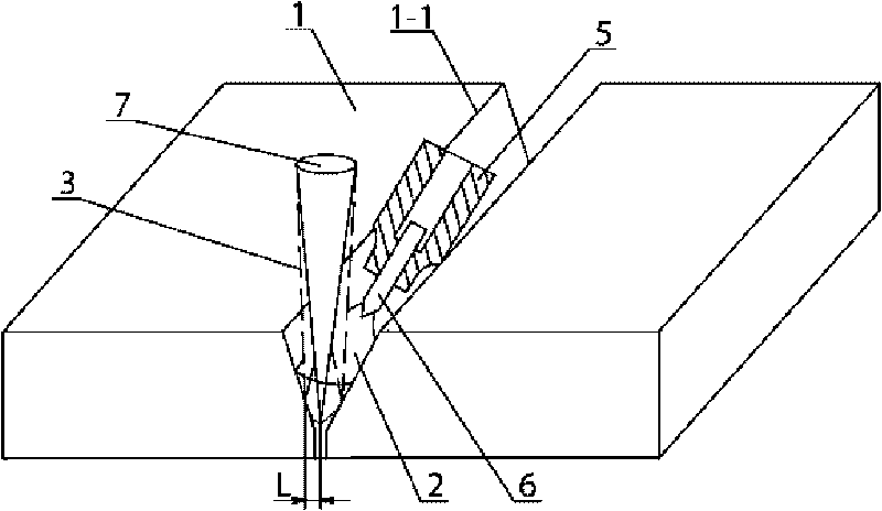
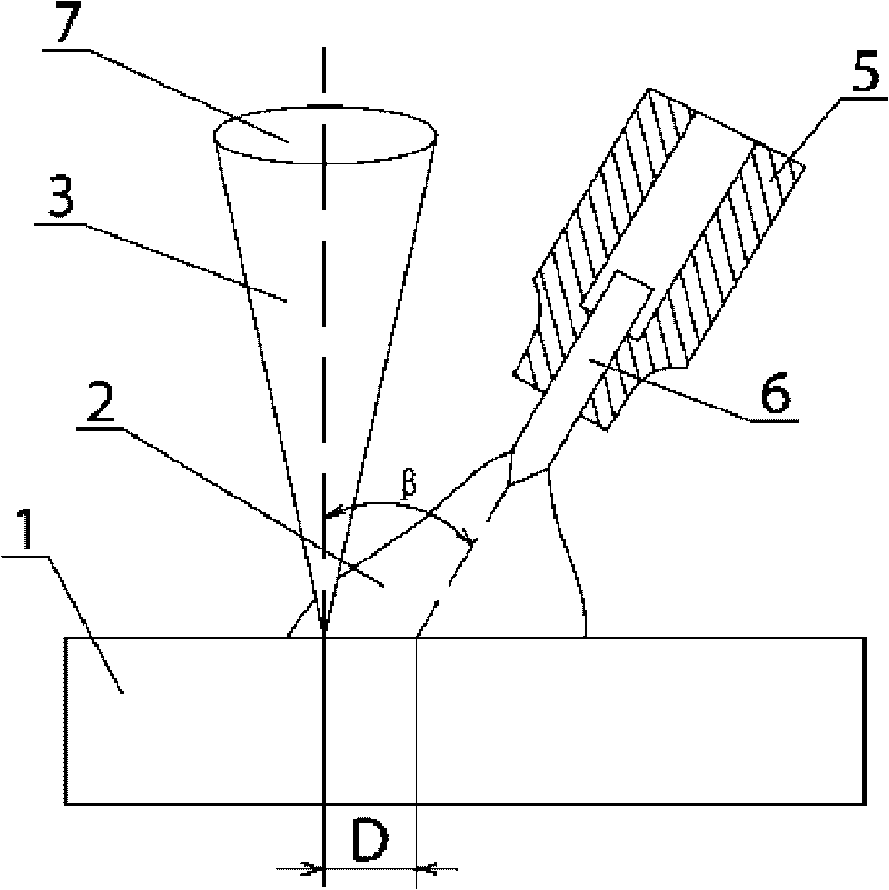
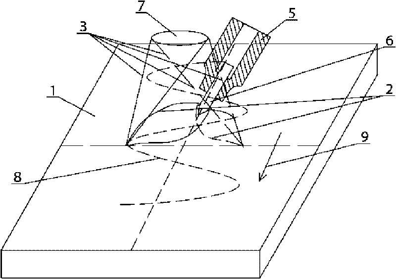
[0007] Specific implementation mode one: combine Figure 1 ~ Figure 3 Describe this embodiment, this embodiment is realized through the following steps: Step 1: beveling: bevelling 1-1 at the welding position of the workpiece 1 to be welded; Step 2: clamping the workpiece 1 to be welded: placing the welder Part 1 is fixed on the fixture; Step 3: Determine the position of the arc 2 and the laser beam 3: adjust the position of the laser-GMA arc hybrid welding device so that the laser beam 3 is perpendicular to the surface of the workpiece 1 to be welded, and the arc 2 and the laser beam The angle β between 3 is 15-60°, the distance D between the laser beam 3 and the tip of the GMA arc welding wire 6 is 2-6mm; step 4: set the welding process parameters: the laser power is 800-5000W, the welding current The gas flow rate of the GMA arc welding torch is 10-30L / min, the dry elongation of the GMA arc welding wire 6 is 15-20mm, the diameter of the GMA arc welding wire 6 is 1.0-1.6mm, ...

specific Embodiment approach 2

[0008] Specific implementation mode two: combination figure 1 To describe this embodiment, the shape of the groove in Step 1 of this embodiment is U-shape or Y-shape. On the one hand, this design is beneficial to the absorption of laser energy during the hybrid welding process; on the other hand, it is beneficial to avoid the occurrence of sidewall incomplete fusion defects. Other steps are the same as in the first embodiment.

specific Embodiment approach 3

[0009] Specific implementation mode three: combination figure 1 To describe this embodiment, the angle β between the arc 2 and the laser beam 3 in Step 3 of this embodiment is 45°. When the included angle β between the arc 2 and the laser beam 3 is 45°, it is the best angle for the laser beam to be oscillatingly welded on the workpiece 1 to be welded. Other steps are the same as in the first embodiment.


PUM

PropertyMeasurementUnit
lengthaaaaaaaaaa
diameteraaaaaaaaaa
lengthaaaaaaaaaa

Abstract

The invention discloses a method for realizing swing welding with a laser-GMA electric arc hybrid welding device, relating to a laser-melting electrode gas metal arc welding hybrid welding method. The method solves the problem that the defects such as incomplete fusion, gas hole and included slag, and the like, are easily existed between a side wall and a layer when welding a moderate plate and a thick plate with the laser-GMA electric arc hybrid welding device. The method comprises the following steps of: 1. chamfering; 2. clamping a work piece to be welded; 3. ensuring the positions of an electric arc and a laser beam, wherein the laser beam is perpendicularly irradiated to the surface of the work piece to be welded, an included angle between the electric arc and the laser beam is 15-60 DEG C, and the distance between the laser beam and the sharp end of a GMA electric arc welding wire is 2-6mm; 4. setting a welding technology parameter; and 5. performing the welding, wherein an electric arc welding gun is kept to be immovable when welding, and a laser beam-focused wielding gun swinging welds in the shape of 'S'. The method is used for butt welding of a thick plate more than 10mm in national defense and civil use fields of shipbuilding, petroleum pipe lines, high-pressure vessels, fighting vehicles and nuclear devices, etc.

Description

technical field [0001] The invention relates to a laser-melting electrode gas shielded welding composite welding method. Background technique [0002] In the past, the welding of medium and thick plate high-strength steel widely used in the fields of ships, oil pipelines, high-pressure vessels, railway vehicles, national defense and civil industry all adopts the traditional arc welding method, which not only has low welding efficiency, but also has low weld strength and heat loss. If the input is large, the welding deformation will be large. The laser-GMA arc hybrid welding device (GMA is gas metal shielded welding) is an effective way to achieve high efficiency and low cost for medium and thick-walled components. The laser-GMA arc hybrid welding device can weld various metal materials. Due to the use of laser-GMA The arc hybrid welding device has the advantages of fast welding speed (several times that of traditional arc welding), small welding deformation, long beam dista...

Claims


Application Information

Patent Timeline
Patent Type & Authority Applications(China)
IPC IPC(8): B23K28/02
CPCB23K26/1429B23K26/24B23K26/1452B23K26/1438B23K26/348
Inventor 陈彦宾雷正龙
Owner HARBIN INST OF TECH
Why Eureka
Try Eureka