Pulse-detecting circuit used for ultrasonic gas flowmeter based on time difference method

A gas flow meter and ultrasonic technology, applied in the direction of liquid/fluid solid measurement, flow measurement/mass flow measurement, measurement devices, etc., can solve problems such as complex circuits, violations, and high software overhead, and achieve simple and reasonable structure of the circuit , fast response effect

Inactive Publication Date: 2010-06-02
NANJING UNIV
View PDF0 Cites 18 Cited by
  • Summary
  • Abstract
  • Description
  • Claims
  • Application Information

AI Technical Summary

Problems solved by technology

Therefore, automatic gain control needs to write special software for AD sampling, and determine the next gain after sampling, and output to DA, which increases the system time overhead, especially for small flowmeters that only use a single-chip system, the system time overhead and The storage space required by AD takes up more resources, and has high requirements for software reliability; on the other hand, in the process of AD and DA conversion, it will inevitably be accompanied by loss of precision, which directly affects the automatic gain. The peak value of the signal fluctuates, and even causes the peak value to fluctuate too much,

Method used


Image

  • Pulse-detecting circuit used for ultrasonic gas flowmeter based on time difference method
  • Pulse-detecting circuit used for ultrasonic gas flowmeter based on time difference method
  • Pulse-detecting circuit used for ultrasonic gas flowmeter based on time difference method

Examples


Embodiment Construction

[0025] The present invention will be further described below in conjunction with the accompanying drawings.

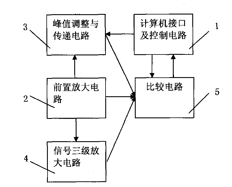
[0026] Such as figure 1 As shown, a signal detection circuit for a time-difference method ultrasonic gas flowmeter of the present invention includes a computer interface and a control circuit 1, a preamplifier circuit 2, a peak value adjustment and transfer circuit 3, a signal three-stage amplifier circuit 4 and a comparison Circuit 5. The preamplifier circuit 2 is electrically connected to the peak adjustment and transfer circuit 3 and the signal three-stage amplifying circuit 4 respectively, and the preamplifier circuit 2, the peak adjustment and transfer circuit 3 and the signal three-stage amplifying circuit 4 are respectively passed through The comparison circuit 5 is electrically connected to the computer interface and the control circuit 1; the synchronous signal input by the computer interface and the control circuit 1 controls the working sequence of the circ...


PUM

PropertyMeasurementUnit
Input resistanceaaaaaaaaaa

Abstract

The invention discloses a pulse-detecting circuit used for an ultrasonic gas flowmeter based on a time difference method. The pulse-detecting circuit is characterized by comprising a computer interface, a control circuit, a pre-amplification circuit, a peak value adjusting and transmitting circuit, a signal three-level amplification circuit, and a comparison circuit; wherein the pre-amplification circuit is respectively connected with the peak value adjusting and transmitting circuit and the signal three-level amplification circuit; and the pre-amplification circuit, the peak value adjusting and transmitting circuit and the signal three-level amplification circuit are electrically connected through the comparison circuit and the computer interface as well as the control circuit respectively. By adopting a peak value transmission method, the invention automatically changes a comparative level used for generating a zero-crossing comparison control signal according to changes of the peak value of a signal, avoids complex controls needed by a gain control, and simplifies a circuit structure to be very simple; and moreover, the invention avoids precision loss generated during conversion and a balanced contradiction between cost and precision without adopting AD/DA conversion.

Description

technical field [0001] The invention relates to a pulse detection circuit for a time-difference method ultrasonic gas flowmeter, which is used for detecting the ultrasonic signal received by the ultrasonic transducer, and outputting an ultrasonic pulse arrival signal when the required pulse is detected. Background technique [0002] Ultrasonic gas flowmeter is used for flow measurement in gas transmission pipelines, mainly used in natural gas pipelines and industrial gas pipelines, and can be divided into Doppler type and time difference method. The ultrasonic gas flowmeter using the time difference method, through a pair of ultrasonic sensors, respectively measures the ultrasonic propagation time between the two in the downstream (relative to the direction of gas flow) and countercurrent, and can calculate the sound velocity, gas flow velocity, and gas flow rate in the pipe section. flow and other parameters. For the ultrasonic gas flowmeter measured by the time-of-flight ...

Claims


Application Information

Patent Timeline
IPC IPC(8): G01F1/66
Inventor 贲宇张仲宁张淑仪
Owner NANJING UNIV
Why Eureka
Try Eureka