
Method and device for directionally emitting sound wave with high sound intensity

A technology of sound wave emission and loud sound, which is applied in the direction of sound-emitting devices and instruments, can solve the problems of difficult sound wave emission with high sound intensity, low energy conversion efficiency, serious harmonic distortion, etc., and achieve light weight, high energy conversion efficiency, small size effect

Active Publication Date: 2010-06-02
IOASONIC SU ZHOU TECH CO LTD
View PDF0 Cites 41 Cited by
  • Summary
  • Abstract
  • Description
  • Claims
  • Application Information

AI Technical Summary

Problems solved by technology

However, due to the limitation of the physical principle of ultrasonic nonlinear action, the energy conversion efficiency of this method is very low, it is difficult to realize the emission of high-intensity sound waves, and its harmonic distortion is also very serious

Method used


Image

  • Method and device for directionally emitting sound wave with high sound intensity
  • Method and device for directionally emitting sound wave with high sound intensity
  • Method and device for directionally emitting sound wave with high sound intensity

Examples


Embodiment Construction

[0065] Below in conjunction with accompanying drawing and specific embodiment, the present invention is described in further detail:

[0066] The present invention utilizes the principle that the sound source array can obtain stronger directivity, cooperates with the array signal processing, that is, the beamforming technology, so as to realize the long-distance directional transmission of the audio sound.

[0067] First, a method for emitting high-intensity directional sound waves provided by the present invention will be described in detail. This method needs to pre-train the system to obtain the transfer function of the loudspeaker array, which is reserved as the basis for parameter selection during signal processing. For those skilled in the art, this pre-training method is a conventional method of signal processing, so it will not be described in detail.

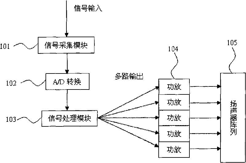
[0068] A method of high-intensity directional acoustic emission, such as figure 1 shown, including the following st...


PUM


Abstract

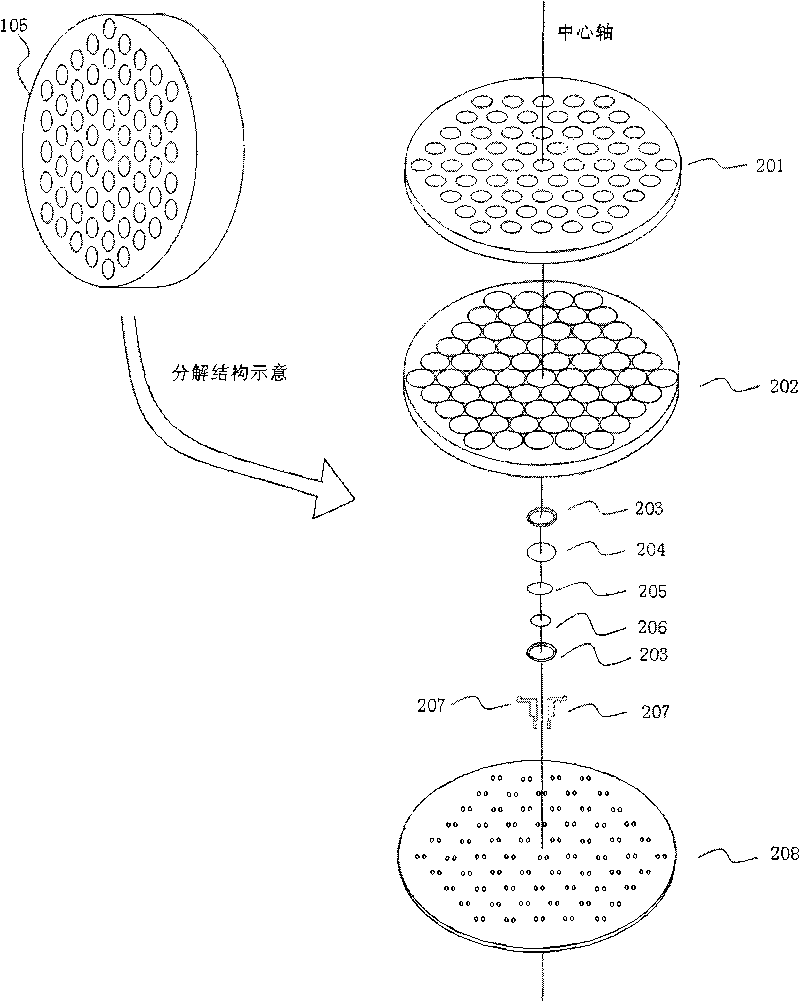
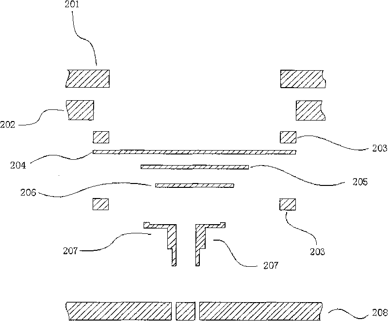
The invention relates to a method and a device for directionally emitting sound waves with high sound intensity. In the method, an array signal processing circuit is adopted to respectively drive multiple paths of loudspeaker arrays to realize remote directional transmission of the high sound intensity sound waves. Signal processing comprises three processing parts which are frequency division processing, frequency band pre-weighting processing and wave bundle forming processing. Firstly, broadband digital signals are decomposed into a plurality of sub frequency band signals through the frequency division processing; secondly, based on a psychoacoustic mold, each sub frequency band signal subjects to gain adjustment through the frequency band pre-weighting processing according to psychoacoustic parameters; and finally, the phase of input signals of each path of small array is adjusted through the wave bundle forming processing, and output sounds of each path are equidirectionally superposed at a far field position so as to enhance the directivity. In the device, the array signal processing circuit is adopted to respectively drive multiple paths of the loudspeaker arrays and an integral type piezoelectric ceramic transducer array so as to realize the remote and directional transmission of the high sound intensity sound waves.

Description

technical field [0001] The invention relates to directional sound transmission technology, in particular to a method and device for high sound intensity directional sound wave emission. Background technique [0002] Directional sound transmission has a wide range of applications in real life. Directional sound transmission technology is to transmit sound waves in a bundled manner, which is to make the sound source directional. For example, if two adjacent showcases in the exhibition hall use directional sound sources to introduce the exhibits, then their respective audiences can hear the introduction of the exhibits they are visiting without interfering with each other. However, in some occasions, not only sound waves need to be capable of directional propagation, but sound waves also need to be capable of long-distance propagation, that is, the sound source can emit high-intensity sound waves, such as: military and police remote sound wave warning, suppression, long-distanc...

Claims


Application Information

Patent Timeline
IPC IPC(8): G10K11/18
Inventor 杨军张维吴鸣
Owner IOASONIC SU ZHOU TECH CO LTD
Learn More