Supercharge Your Innovation With Domain-Expert AI Agents!

Resistance reduction block

A technology of reducing resistance and ions, applied in the direction of connecting contact materials, etc., can solve the problems of environmental pollution caused by gelling agents and preservatives, troublesome construction, and unsatisfactory resistance reduction effect, and achieve the maintenance and improvement of soil moisture, construction and stability. The effect of easy reconstruction and reduction of soil resistivity

Inactive Publication Date: 2010-06-02
刘义 +1
View PDF0 Cites 0 Cited by
  • Summary
  • Abstract
  • Description
  • Claims
  • Application Information

AI Technical Summary

Problems solved by technology

[0004] Many manufacturers of grounding products tend to think of ways around the grounding device, not only the effect is limited, but also there are many problems in the implementation process: one is to lay the resistance reducing agent around the grounding body, the resistance reducing agent is either easily lost by the rain, or Corrosion of the grounding body makes the ground resistance unstable. Some gels and preservatives used in the resistance reducing agent will also pollute the environment, and the resistance reducing agent can only reduce the soil resistivity of the local area centered on the grounding device. The effect is very limited when it comes to large-scale grounding grids with high soil resistivity; the second is to use copper ion grounding rods to reduce grounding resistance, which is expensive, troublesome to construct, and the effect of reducing resistance is not very ideal, and there is also the problem of carrier (copper pipe) corrosion , once the carrier (copper tube) is corroded, the ionic material will be lost quickly, and the ground resistance will rebound. In addition, the copper will also pollute the environment after corrosion

Method used


Image

  • Resistance reduction block
  • Resistance reduction block
  • Resistance reduction block

Examples


Embodiment Construction

[0017] In order to make it easier for those skilled in the art to understand, we will describe the present invention in more detail below in conjunction with the drawings and specific embodiments.

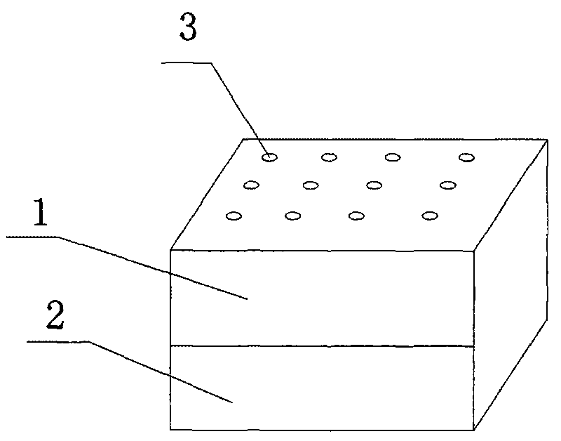
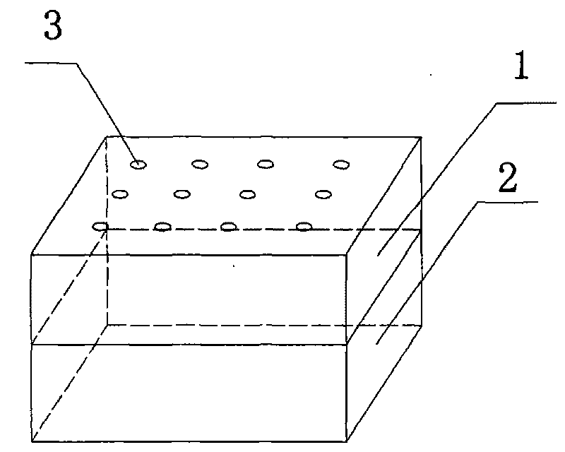
[0018] refer to Figure 1 to Figure 4 , the resistance-reducing block, the resistance-reducing block is at least composed of a water storage box 1 and an ion chamber 2. The ion chamber 2 and the water storage box 1 can be integrated or split. The ion cabin and the water storage box are made of non-metallic materials with pores.

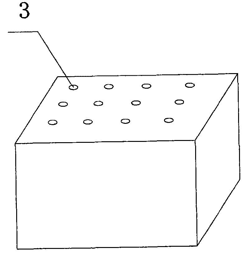
[0019] The interior of the water storage box 1 is a chamber structure, and at least one cavity is provided; the upper surface of the water storage box 1 has many small water inlet through holes 3, and the shape of the water inlet holes can be set according to needs, and can be any shape. So that after the resistance reducing block is buried in the soil, it can collect rainwater or absorb soil moisture at any time and store it in the water storage box 1, ...


PUM


Abstract

The invention discloses a resistance reduction block. The resistance reduction block comprises an ion chamber, wherein the inside of the ion chamber has a chamber structure and contains at least one cavity, and conducting ionic material is arranged in the cavity. The beneficial effect of the invention is as follows: the resistance reduction block is not limited by the earthing device such as the earthing electrode and the earthing body, the use number can only be determined based on the requirement for reducing the soil resistance in the whole region of the grounding grid and the embedding position and spacing of the resistance reduction blocks can be determined by the specific conditions of the use number and the local soil, thus the resistance reduction block is convenient and flexible to use; the product can significantly improve the soil resistance in the grounding grid construction area and effectively stabilize the earth resistance value of the grounding grid for long time; the corrosion of the metal earthing device is reduced, the service life of the earthing system is significantly increased; and the resistance reduction block has the long-term effectiveness, thus the maintenance cost of the grounding grid can be obviously reduced.

Description

technical field [0001] The invention relates to the fields of lightning protection and safe electricity utilization, in particular to a resistance reducing block for reducing soil resistivity. Background technique [0002] It can be seen from the calculation formula of the vertical grounding body, horizontal grounding body, and the grounding resistance of the grounding network that reducing the soil resistivity ρ in the area where the grounding network is located is the key to reducing the grounding resistance. [0003] At present, the methods for improving soil resistivity are as follows: one is to adopt the method of soil replacement, when large-scale soil replacement involves land excavation and soil transportation, the cost is too high, sometimes the soil is taken from a long distance, and it is difficult to implement; Spraying chemical grounding resistance reducing agent has no obvious spraying effect on the soil surface, and it is also unrealistic to spray in the deep ...

Claims


Application Information

Patent Timeline
Patent Type & Authority Applications(China)
IPC IPC(8): H01R4/66
Inventor 王文刚
Owner 刘义
Features
  • R&D
  • Intellectual Property
  • Life Sciences
  • Materials
  • Tech Scout
  • Unparalleled Data Quality
  • Higher Quality Content
  • 60% Fewer Hallucinations
Learn More