Impeller structure of rotary shell type pump

A technology of impeller and rotary casing, which is applied in the field of pump impeller structure, can solve problems such as unstable operation, impact loss, hydraulic loss, etc., and achieve the effects of low roughness, guaranteed dimensional accuracy, and guaranteed uniformity

Inactive Publication Date: 2010-06-09
JIANGSU UNIV
View PDF0 Cites 10 Cited by
  • Summary
  • Abstract
  • Description
  • Claims
  • Application Information

AI Technical Summary

Problems solved by technology

These effects produce hydraulic losses both within the impeller and in the fluid leaving the impeller
The radial straight-flow channel impellers for rotary casing pumps proposed by some developed countries inev

Method used


Image

  • Impeller structure of rotary shell type pump
  • Impeller structure of rotary shell type pump
  • Impeller structure of rotary shell type pump

Examples


Embodiment Construction

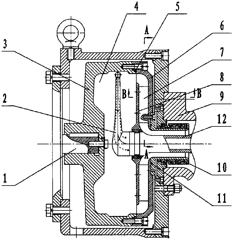
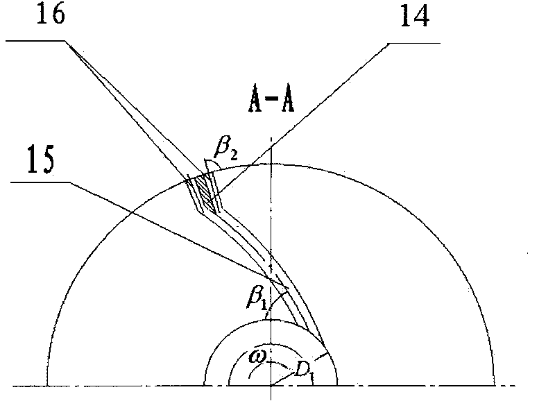
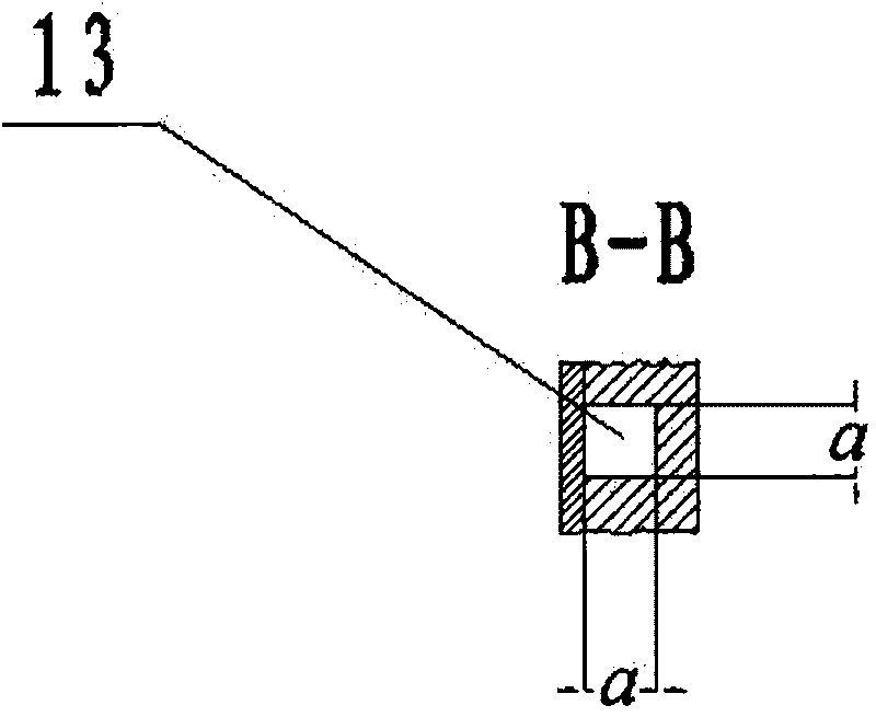
[0018] A high-efficiency rotary shell pump impeller structure includes impeller blades located between a front cover plate 6 and a rear cover plate 8. Adjacent impeller blades form an impeller flow channel 7, and the impeller flow channel 7 and the front cover plate 6 are integrated. The impeller suction section 9, the front cover 6 and the rear cover 8 can all use casting blanks. The material can be cast iron or cast steel according to the design parameters. Most of the petrochemical industry uses stainless steel. Both the rear cover 8 and the suction section 9 can reach the size required by the design through a gold processing method. The front cover 6 is the main body of the impeller. The outer diameter of the impeller outlet is calculated according to the design flow, head and speed, as well as the number of impeller runners 7 and the cross-sectional dimensions of the runners. According to the inlet runner size a, the inlet of the runner is initially determined The diameter...


PUM


Abstract

The invention discloses an impeller structure of a rotary shell type pump, which comprises impeller blades positioned between a front cover plate and a back cover plate. The adjoining impeller blades are formed into impeller flow passageways. The impeller structure is characterized in that each impeller flow passageway consists of an impeller inlet flow passageway and an impeller outlet flow passageway; each impeller inlet flow passageway is an arc flow passageway, wherein the length of the arc flow passageway is 60-70% of that of the impeller flow passageway, and an inclined angle beta1 arranged between the midline of each impeller inlet flow passageway and an inlet distribution circle is from 20 to 40 degrees; and each impeller outlet flow passageway is provided with two outlet radial branch flow passageways. The impeller flow passageways of the impeller structure effectively restrains the generation of axial whirlpool and flow separation; a smaller inlet angle can lead the impact loss of the inlet to be reduced; the branch of the outlet flow passageway leads the liquid which flows into a shell to be more even; and the milling machine of the flow passageways can obtain small surface roughness to achieve the aim for improving the waterpower efficiency of the impeller.

Description

Technical field [0001] The invention relates to an impeller structure of a pump. Specifically refers to the impeller structure of a low specific speed pump that is used to transport liquids with small flow and high head requirements. The specific speed range of the above low specific speed pump is n s = 8~60. Background technique [0002] With the requirements of reduced flow and increased lift, the specific speed of the pump continues to decrease. When specific speed n s When it is lower than 20, usually the efficiency of the centrifugal pump will drop below 30%. In the range of vane pumps, it is generally designed as a partial flow pump. At present, in the domestic design of fixed-shell high-speed partial flow pump impeller, single-stage open impeller structure and closed long and short blade impeller structure are generally adopted. The impeller and the casing of the rotary shell partial flow pump rotate together. Most designs at home and abroad use semi-open impeller and c...

Claims


Application Information

Patent Timeline
IPC IPC(8): F04D29/22
Inventor 杨敏官康灿张峰肖胜男
Owner JIANGSU UNIV
Why Eureka
Try Eureka