Method for producing holographic double balzed grating

A blazed grating and holographic technology, which is applied in the field of diffractive optical element preparation, can solve problems such as large surface roughness and surface shape errors, ghost lines, and difficult double blazed grating structure, and achieve the effect of ensuring consistency

Active Publication Date: 2010-06-09
SUZHOU UNIV
View PDF0 Cites 27 Cited by
  • Summary
  • Abstract
  • Description
  • Claims
  • Application Information

AI Technical Summary

Problems solved by technology

However, as mentioned above, when the blazed grating is produced by the mechanical scribing method, ghost lines will be generated, and the surface roughness and surface shape errors are large, while the electron beam direct writing method is long in production ti

Method used


Image

  • Method for producing holographic double balzed grating
  • Method for producing holographic double balzed grating
  • Method for producing holographic double balzed grating

Examples


Embodiment 1

[0052] Embodiment 1: The method for making a holographic double blazed grating with a grating period of 833 nanometers and two blaze angles of 10° and 25° respectively, is realized by two interference exposures and two ion beam etching methods, including the following steps: ( Rectangular photoresist grating mask)

[0053] (1) Coating photoresist on the quartz substrate, according to the requirements of the double blazed grating that needs to be made, that is, the grating period (Λ) is 833 nanometers, and the two blazed angles are 10° and 25° respectively. According to the empirical formula of blaze angle θs and groove shape and ion beam incident angle, θs≈α-3°.

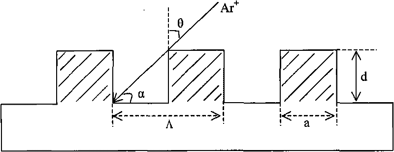
[0054] Using a rectangular photoresist grating (see attached image 3 ) as an example, first make a 10° blaze angle (A blaze angle) grating, generally, the duty ratio f=a / Λ=0.5, by the formula tgα = d Λ - a = ...

Embodiment 2

[0066] Embodiment 2: The method for making a holographic double blazed grating with a grating period of 1000 nanometers and two blaze angles of 10° and 25° respectively, is realized by two interference exposures and two ion beam etching methods, including the following steps: ( Triangular photoresist grating mask, see attached Figure 5 shown)

[0067] (1) Coating photoresist on the quartz substrate, according to the requirements of the double blazed grating that needs to be made, that is, the grating period (Λ) is 1000 nanometers, and the two blazed angles are 10° and 25° respectively. According to the empirical formula of blaze angle θs and groove shape and ion beam incident angle, θs≈α-3°.

[0068] Taking the triangular photoresist grating as an example, first make a 10° blaze angle (A blaze angle) grating, the general duty ratio f=a / Λ=0.5, by the formula tgα = d Λ - a ...

Embodiment 3

[0080] Embodiment 3: The method for making a holographic double blazed grating with a grating period of 1000 nanometers and two blaze angles of 12 degrees and 25 degrees respectively, is realized by two interference exposures and two ion beam etching methods, including the following steps: ( Sinusoidal photoresist grating mask, see attached Figure 6 shown)

[0081] (1) Coating photoresist on the quartz substrate, according to the requirements of the double blazed grating that needs to be made, that is, the grating period (Λ) is 1000 nanometers, and the two blazed angles are 12° and 25° respectively. According to the empirical formula of blaze angle θs and groove shape and ion beam incident angle, θs≈α-3°.

[0082] Take the sinusoidal photoresist grating as an example (the outline of the grating is as attached Figure 6 shown), first make a 12° blaze angle (A blaze angle) grating, the duty ratio of the grating is f=a / Λ=0.5, and the profile of the grating can be expressed by th...


PUM


Abstract

The invention discloses a method for producing a holographic double balzed grating, which is characterized in comprising the steps of: (1) coating a photoresist on a substrate of the grating; (2) performing a first interference lithography to produce a photoresist grating mask which is accordant with the requirement of an A balze angle; (3) scanning and etching the grating mask of an A grating area with angled Ar ion beam to be formed into a triangular groove shape of a balzed grating, and washing the substrate; (4) recoating the photoresist; (5) shielding a B grating area, aligning by means of moire pattern with the prepared A grating area, removing the shield, and performing a second interference lithography to produce a photoresist grating mask which is accordant with the requirement of a B balze angle; (6) scanning and etching with the angled Ar ion beam, so that the B grating area is formed into the triangular groove shape of the balzed grating; and (7) washing the substrate to obtain the holographic double balzed grating. The method realizes the production of the holographic double balzed grating, thereby being capable of exactly and respectively controlling the two balze angles.

Description

technical field [0001] The invention relates to a preparation method of a diffractive optical element, in particular to a preparation method of a holographic double blazed grating. Background technique [0002] Grating is a very widely used and important high-resolution dispersive optical element, which occupies a very important position in modern optical instruments. [0003] As we all know, the principal maximum direction of diffraction by a single grating is actually not only the geometrical optics propagation direction of light, but also the zero-order direction of the entire multi-slit grating. It concentrates light energy, but cannot separate various wavelengths. In practical applications, Focus on concentrating as much light energy as possible on a specific order. For this reason, it is necessary to make the diffraction grating into a groove shape determined by calculation, so that the main maximum direction of the diffraction of a single grating groove (or the direc...

Claims


Application Information

Patent Timeline
IPC IPC(8): G02B5/18G03F7/00
Inventor 刘全吴建宏汪海宾胡祖元陈新荣李朝明
Owner SUZHOU UNIV
Why Eureka
Try Eureka