Manufacturing method and structure of camber-shaped capacitance type touch-control plate

A capacitive touch, curved surface technology, applied in electrical digital data processing, data processing input/output process, instruments, etc., can solve the problems of weak stress strength, broken substrate, become waste, etc., to achieve easy shape control , The effect of reducing processing difficulty and product quality assurance

Active Publication Date: 2010-06-09
TPK ADVANCED SOLUTIONS
View PDF4 Cites 48 Cited by
  • Summary
  • Abstract
  • Description
  • Claims
  • Application Information

AI Technical Summary

Problems solved by technology

[0003] It is known that the current optoelectronic products will be advanced with curved surface design as the mainstream; therefore, when designing the product, adding some physical buttons and art seams on the surface will cause the curvature of the product surface to be uncoordinated, and increase the surface area. The difficulty of designing and manufacturing the curved surface; in addition, related technologies related to the above-mentioned curved surface products can be found in British Patent No. 1110377, Japanese Patent No. 2002341323, Chinese Patent No. 1612185 (publication number), and AU Optronics Co., Ltd. The company (AUO PTRONIC SCORP.) publicly announced and demonstrated the convex curved liquid crystal display in June 2008; however, the described technology is about the curved surface application of safety glass or LCD, and neither mentions the curved surface application of the touch panel
[0004] In view of this, in the more advanced technology, related technologies related to the design of the curved surface of the above-mentioned touch panel have been disclosed. It can be seen in US Patent No. 6,654,071, which provides a display that can be freely bent according to the curvature of the display surface. A curved flexible capacitive touch panel is used to attach to the surface of the display, so that the display has a touch function; in addition, Chinese Patent No. 1479891 (publication number) also provides a The curved capacitive touch pad is provided with a functional film between two curved rigid transparent protective plates, and has touch capability; however, the touch pad of U.S. Patent No. 6,654,071 and the touch pad of Chinese Patent No. 1,479,891 All can only be bent into a curved surface along one axis (such as the longitudinal axis or horizontal axis of the touch panel), but cannot form a curved surface with multiple axes, and the touch panel and the touch panel described above are not disclosed. pad; therefore, there are still many technical problems to be overcome in order to make the above-mentioned touch panel into a curved shape
[0005] In order to overcome the above problems, U.S. Patent No. 20080042997 discloses a curved resistive touch panel. The main method is to firstly attach the plane polarizer to the touch panel, and then simultaneously press the polarizer and the touch panel to form a curved surface. ; Its disadvantage is that if the polarizing plate and the touch panel fail to be pressurized, both of them will become waste materials, and the polarizing plate and the touch panel are in a state where a plurality of base materials are bonded to each other. In the process of forming a curved surface, it is easy to cause partial fracture of the base material with weak stress intensity, and at the same time, it is easy to generate interference stripes, which become waste materials that fail to pressurize, so it is urgent to improve
[0006] In addition, most of the existing flat touch panels use glass materials as substrates. Compared with plastic materials (such as PET), they have better light penetration, scratch resistance, wear resistance, and less deformation. If glass substrates are to be made into Curved surface, the glass substrate needs to be subjected to high temperature hot pressing to bend to form a curved glass substrate; however, the production of a curved glass substrate requires a very high working temperature (about 650 to 750 degrees Celsius), and the flexible circuit board is in the It will crack at an operating temperature of about 300 degrees Celsius, so the flexible circuit board obviously cannot be made into a curved touch panel together with the flat glass substrate

Method used


Image

  • Manufacturing method and structure of camber-shaped capacitance type touch-control plate
  • Manufacturing method and structure of camber-shaped capacitance type touch-control plate
  • Manufacturing method and structure of camber-shaped capacitance type touch-control plate

Examples


Embodiment Construction

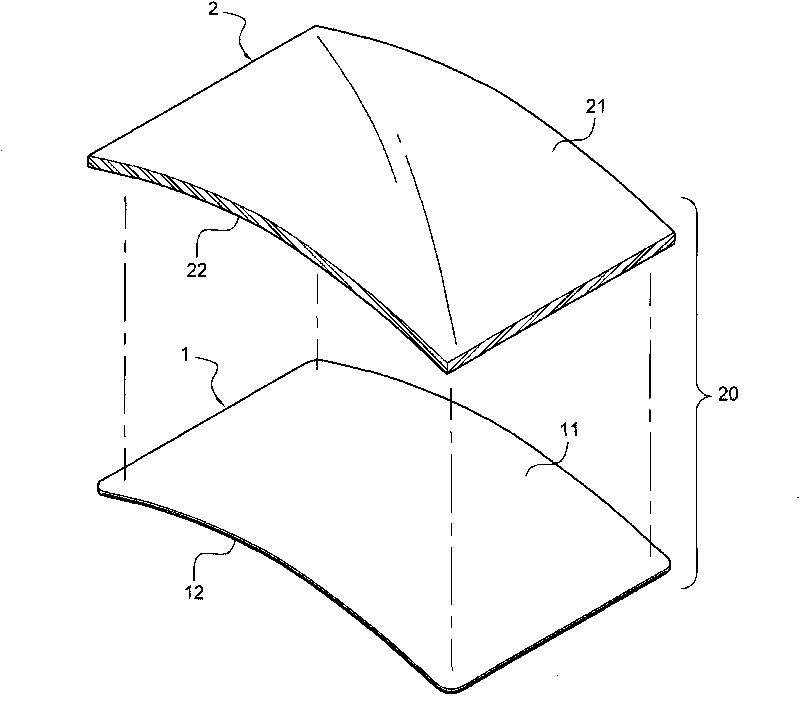
[0053] see figure 1 , revealing a three-dimensional exploded view of an embodiment of the present invention, and cooperate with Figure 2A to Figure 8 Illustrate the preparation method of the curved capacitive touch panel of the present invention, comprise the following steps:

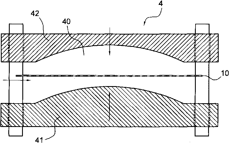
[0054] (1) Provide a planar flexible circuit board 10 with capacitive touch function (such as Figure 2A shown).

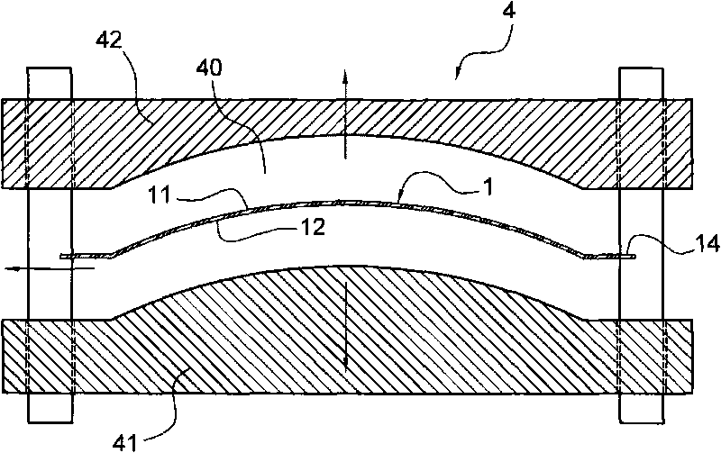
[0055] (2) Forming the flat flexible circuit board 10 with a curved surface by means of molding. In the mold cavity 40 between a male mold 41 of molding device 4 and a female mold 42 (as Figure 2A shown), the male mold 41 and the female mold 42 are preheated to a preset temperature (about 200 to 250 degrees Celsius), and the preset temperature can be used to thermally mold the planar flexible circuit board 10 Molding temperature; in this way, the flat flexible circuit board 10 can be clamped and hot-pressed by the male mold 41 and the female mold 42 to mold the flat flexible circuit b...


PUM


Abstract

The invention provides a manufacturing method and a structure of a camber-shaped capacitance type touch-control plate. The manufacturing method comprises the following steps of: firstly providing a planar flexible circuit board with a capacitance type touch-control function; then compressing and molding the planar flexible circuit board into a camber-shaped flexible circuit board in a compression molding way; then providing a camber-shaped base plate, and coupling and attaching the outer camber of the camber-shaped flexible circuit board to the inner camber of the base plate, thus the camber-shaped capacitance type touch-control plate is assembled.

Description

technical field [0001] The present invention relates to a manufacturing method and structure of a curved capacitive touch panel, in particular to a method for molding a capacitive touch panel into a curved surface, and a touch panel structure made by the method . Background technique [0002] The more common flat touch panels (Touch Panel) now include resistive and capacitive touch panels; among them, the capacitive touch panel has a touch circuit inside, which can use yellow light processes such as exposure, development, and etching. , stacking transparent conductive materials (Indium Tin Oxide, ITO) on the surface of a transparent substrate one by one to form a transparent capacitive touch panel; or, the touch circuit can also be a flexible circuit Board (FLEXBILPRINTED CIRCIT, FPC), the flexible circuit board is directly attached to the substrate to become a non-transparent capacitive touch panel; thus, the touch circuit can be used to interact with the human body The c...

Claims


Application Information

Patent Timeline
Patent Type & Authority Applications(China)
IPC IPC(8): G06F3/044
Inventor 黄俊尧洪博斌
Owner TPK ADVANCED SOLUTIONS
Why Eureka
Try Eureka