
The method of data automatic conversion between dynamic analysis software and finite element analysis software

A technology of kinetic analysis and analysis software, applied in the direction of electrical digital data processing, special data processing applications, instruments, etc., can solve problems such as data cannot be automatically converted

Inactive Publication Date: 2011-12-28
CHINA AGRI UNIV
View PDF1 Cites 0 Cited by
  • Summary
  • Abstract
  • Description
  • Claims
  • Application Information

AI Technical Summary

Problems solved by technology

[0005] The purpose of the present invention is to solve the technical problem that the data cannot be automatically converted between the dynamic analysis software and the finite element analysis software in the prior art, resulting in the inability to perform accurate flexible dynamic analysis and stress-strain analysis of the mechanical system, and proposes a A method for automatic data conversion between dynamic analysis software and finite element analysis software that solves the technical problem of automatic data conversion

Method used


Image

  • The method of data automatic conversion between dynamic analysis software and finite element analysis software
  • The method of data automatic conversion between dynamic analysis software and finite element analysis software

Examples


Embodiment Construction

[0021] The following examples are used to illustrate the present invention, but are not intended to limit the scope of the present invention.

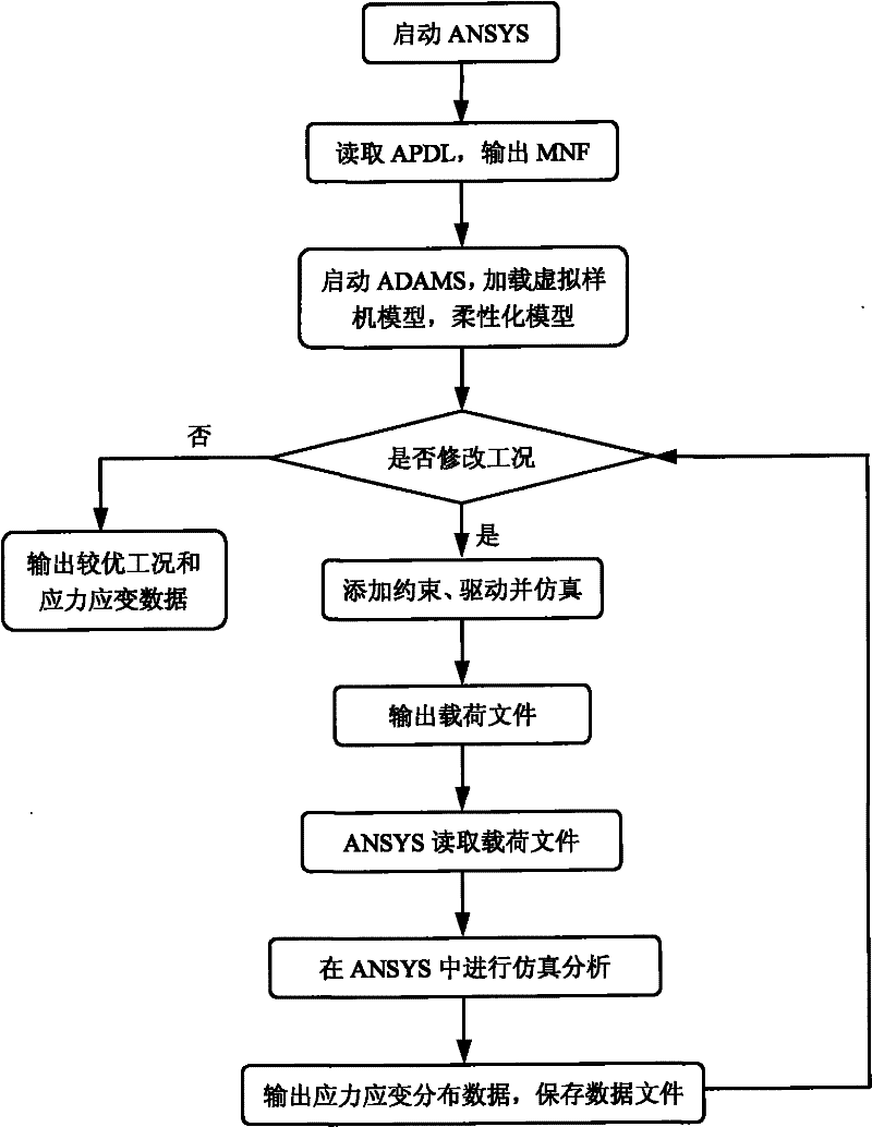
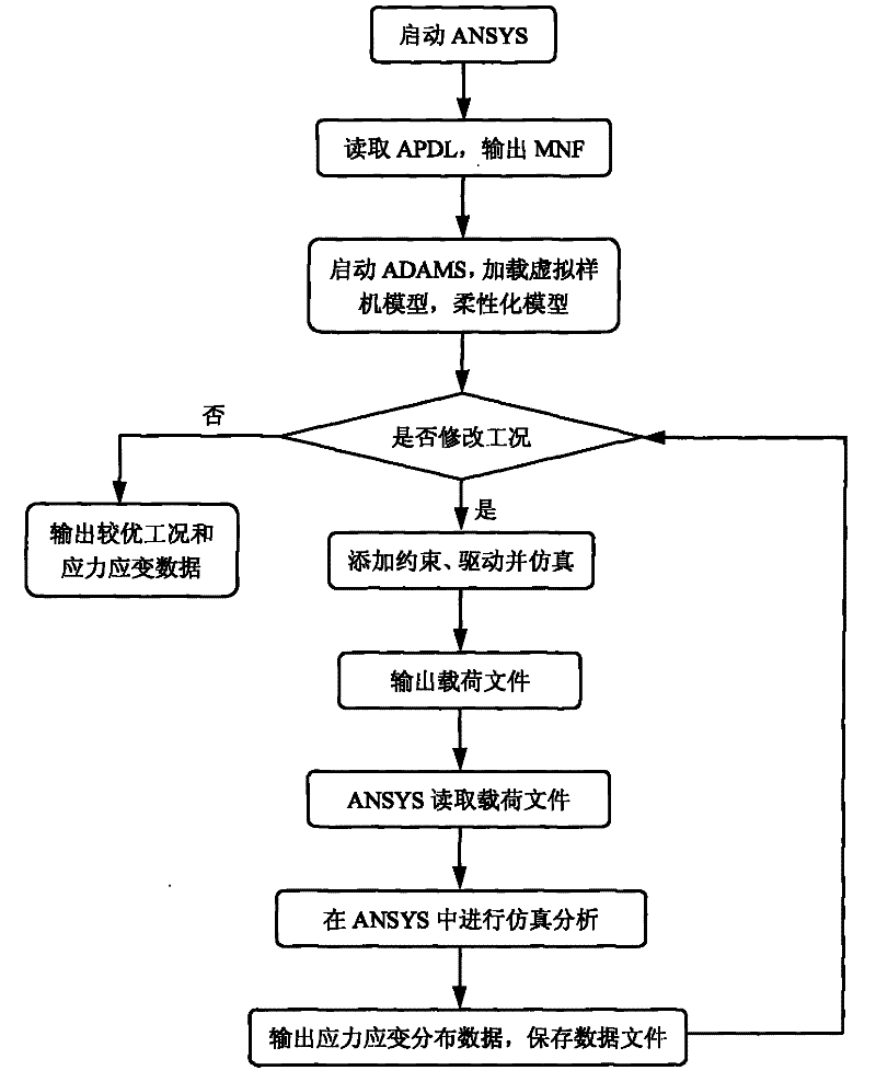
[0022] The technical scheme of the present invention provides a method for data conversion between finite element analysis software and dynamic analysis software. This embodiment takes finite element analysis software ANSYS as the core, figure 1 is its main flow chart, including the following steps:

[0023] (1) First start the finite element analysis software ANSYS directly;

[0024] (2) Utilize the finite element analysis software to read the APDL macro file, the content of the APDL macro file includes: setting up the model of the flexible body part, defining element properties, dividing the grid, defining external nodes, and exporting the required information of the dynamic analysis software The modal neutral file of the flexible body, the modal neutral file contains information such as the mass, center of mass, moment of inertia, ...


PUM


Abstract

The invention discloses a method for automatic data conversion between dynamic analysis and finite element analysis software, comprising the following steps: starting the finite element analysis software for model flexibility, outputting a modal neutral file MNF; starting the dynamic analysis software, Load the virtual prototype model, read the modal neutral file, perform kinematic dynamic analysis, and output the load file; apply the load in the load file to the flexible body to perform stress-strain analysis on the flexible body, and output stress-strain data; loop execution The above steps output the best working condition and stress-strain data. The method for automatic data conversion of the present invention integrates the powerful finite element function of the finite element analysis software and the powerful dynamic analysis function of the dynamic analysis software to truly integrate and jointly use it, and provides a good solution for completing the analysis of the mechanical characteristics of the mechanical system and the analysis of working conditions. An automatic, simple, efficient and reliable means of realization.

Description

technical field [0001] The invention relates to the field of mechanical design, in particular to a method for automatic data conversion between dynamic analysis and finite element analysis software. Background technique [0002] At present, there are many digital engineering design software, each of which is applicable to different professional technical fields, even if they belong to the same field, they have their own characteristics and advantages. The dynamic analysis software can use the computer to create a virtual prototype to simulate the entire motion process of the complex mechanical system, and can analyze the model's force condition and motion state; the finite element analysis software has a powerful finite element analysis function, which can analyze the stress and strain distribution inside the component Wait. At present, the finite element analysis function of dynamic analysis software is limited, and the elastic characteristics of parts can be considered wh...

Claims


Application Information

Patent Timeline
Patent Type & Authority Patents(China)
IPC IPC(8): G06F17/50
Inventor 汤修映肖丹刘川刘岭毛恩荣宋正河娄秀华
Owner CHINA AGRI UNIV
Learn More