Method for manufacturing sectioned die casting inductor

A manufacturing method and segmented mold technology, applied in the manufacture of inductors/transformers/magnets, inductors with magnetic cores, circuits, etc., can solve problems such as deformation or damage, displacement, inductive component yield and performance degradation, etc., to achieve Better inductance characteristics, the effect of increasing magnetic flux

Inactive Publication Date: 2010-06-09
TRIO TECH SUZHOU
View PDF0 Cites 4 Cited by
  • Summary
  • Abstract
  • Description
  • Claims
  • Application Information

AI Technical Summary

Problems solved by technology

Since the coil is not fixed, it is prone to displacement due to extrusion during filling
In addition, because the pressure of the high-pressure process is about 15 to 20 tons per square inch, the coil is easily deformed or damaged when it is directly subjected to such a high pressure, and the yield and performance of the inductor component manufacturing are greatly reduced.

Method used


Image

  • Method for manufacturing sectioned die casting inductor
  • Method for manufacturing sectioned die casting inductor
  • Method for manufacturing sectioned die casting inductor

Examples


Embodiment 1

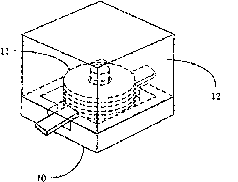
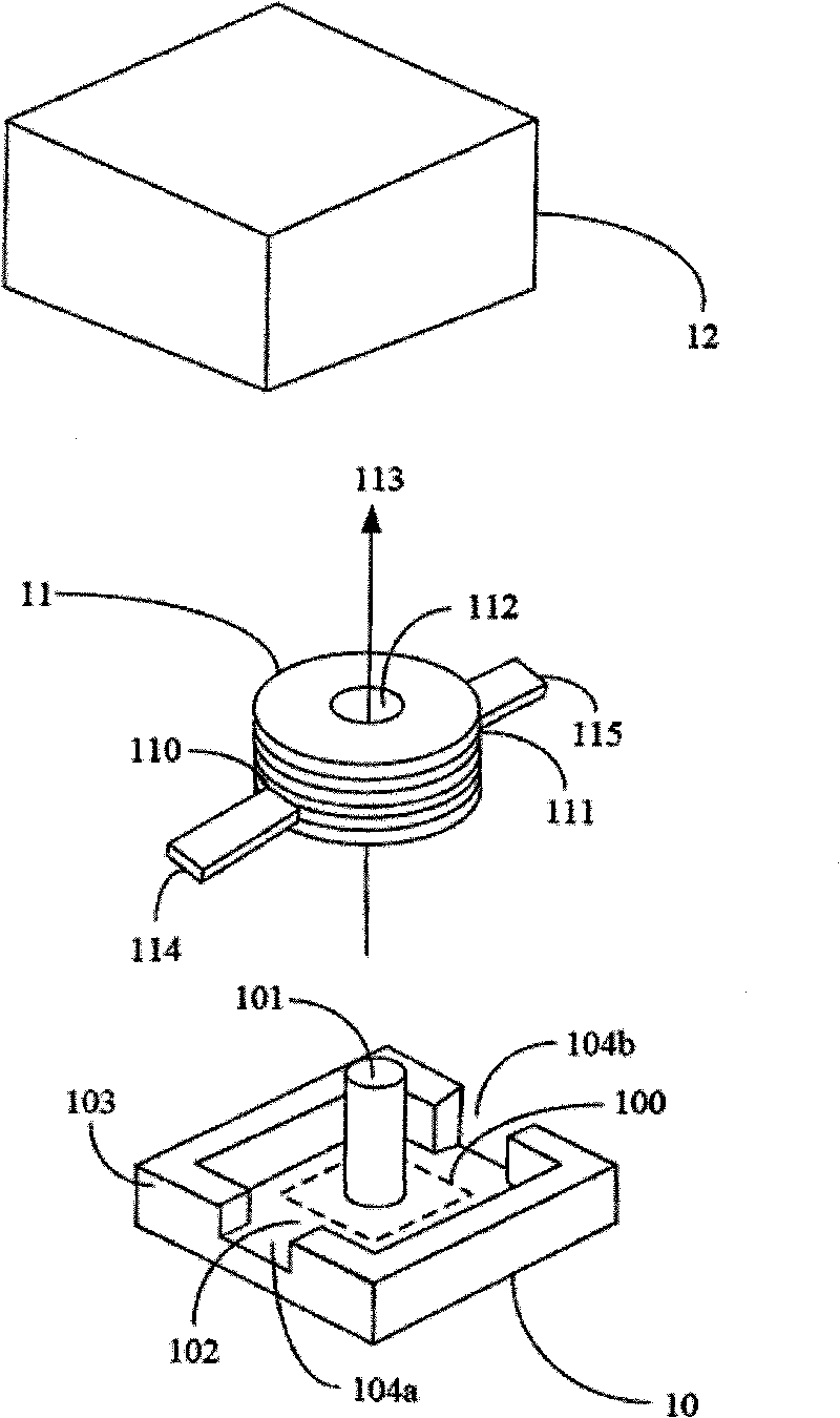
[0029] Such as figure 1 As shown: the segmented molded inductor includes a base 10 formed by the first high-pressure process, a metal coil 11 and a cladding structure 12 formed by the second high-pressure process.

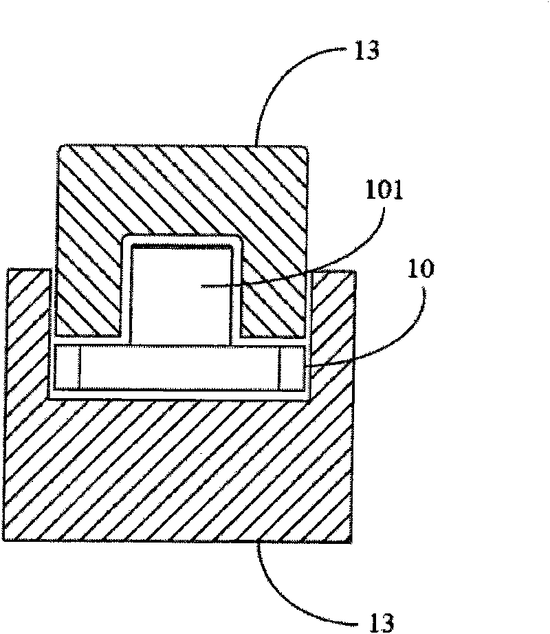
[0030] Specifically, combining figure 2 It can be seen that the central area 100 of the base 10 formed by the high-pressure process in the first stage includes a central pillar 101 . The base 10 is substantially formed by applying a high-pressure process to the first magnetic material. The first magnetic material is usually a substance such as iron powder or non-alloy powder. that is, image 3 As shown, the first magnetic material is inserted into the base mold 13 with a pre-determined shape, and after the base mold fixes its shape, a high pressure is applied to press the first magnetic material into a shape such as figure 2 The base 10 comprising a flat plate 102 and side walls 103 is shown in FIG.

[0031] Looking further, the metal coil 11 includes two end...

Embodiment 2

[0035] Such as Figure 5 , Image 6 As shown: the segmented molded inductor includes a base 20 , a metal coil 21 and a covering structure 22 . The central area 200 of the base 20 includes a central column 201 , and the central column 201 of the base 20 passes through the hollow portion 212 of the metal coil 21 . The base 20 is also provided with a flat plate 202 on which two openings 202a and 202b are formed. The metal coil 21 includes two ends 210 , 211 and a hollow portion 212 , wherein the two ends 210 , 211 extend along a direction parallel to the central axis 213 of the metal coil 21 . The covering structure 22 is combined on the base 20 and the metal coil 21 . The two ends 210, 211 of the metal coil 21 pass through the two openings 202a, 202b of the base 20, and protrude outward respectively.

[0036] It can be seen from the above text description and the accompanying drawings that after adopting the present invention, in the combined forming process of the covering ...


PUM


Abstract

The invention relates to a method for manufacturing sectioned die casting inductor and is characterized by firstly applying high pressure manufacture procedure on primary magnetic material to form a seat, of which the central area is provided with a center pillar; then providing a metal ring comprising a hollow part, penetrating the center pillar through the hollow part of the metal ring to combine the metal ring and the seat; embedding the seat combined with the metal ring into an encapsulation molding die; filling secondary magnetic material by high pressure manufacture procedure to form an encapsulation structure on the metal ring and the seat so as to finally form a die casting inductor structure. By adopting the invention, the seat and the center pillar supply best bearing force and positioning action to the overall formation of the inductor, thus avoiding the defect that extrusion and deformation easily appearing in the formation of the encapsulation structure worsens the properties of the inductor; meanwhile, the center pillar formed by high density magnetic materials can further increase magnetic flux of the metal ring, so that the metal ring has better inductance property.

Description

technical field [0001] The invention relates to a method for manufacturing inductors, in particular to a method for manufacturing segmented die-cast inductors, and belongs to the technical field of basic electrical components. Background technique [0002] Inductor is an important component in the circuit, which can achieve the functions of filtering, energy storage, matching and resonance. With the miniaturization, portability and high-density assembly of electronic products, inductive components have developed rapidly, and under the consideration of electromagnetic compatibility, the elimination of electromagnetic interference of electronic products has become a basic requirement for electronic products. Many countries have stipulated Restricted by laws and regulations, only in compliance with the regulations can they be sold, and more emphasis is placed on the demand and application of inductance. [0003] The current manufacturing method of inductance components is to d...

Claims


Application Information

Patent Timeline
Patent Type & Authority Applications(China)
IPC IPC(8): H01F17/04H01F27/28H01F1/09H01F41/00
Inventor 林伙利
Owner TRIO TECH SUZHOU
Why Eureka
Try Eureka