

Inductive element and buffer circuit using said inductive element
A technology of inductive components and closed magnetic circuit, applied in electrical components, transformer/inductor components, circuits, etc., can solve the problems of increased manufacturing cost of inductive components, low operation efficiency, difficulty in winding automation, etc. Work efficiency, good inductance characteristics, and the effect of easy winding process
- Summary
- Abstract
- Description
- Claims
- Application Information
AI Technical Summary
Problems solved by technology
Method used
Image

Examples
Embodiment 1~4、 comparative example 1~4
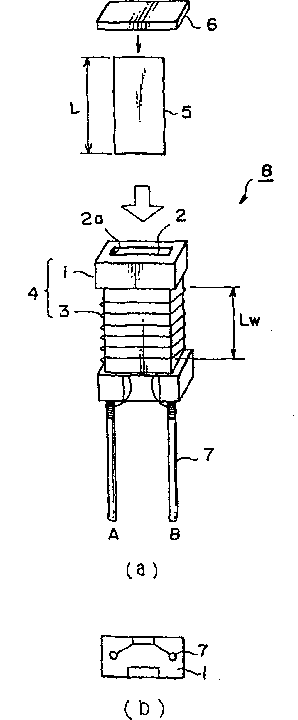
[0105] First, as figure 1 The bobbin 1 shown has a rectangular shape with a height of 15 mm, a width of 6 mm, and a depth of 1.5 mm, and is prepared as a member made of liquid crystal resin (liquid crystal polymer). The opening 2 a of the bobbin 1 has a shape of 5×0.3 mm and a hollow portion 2 with a depth of 14 mm. In addition, two conductors with a square cross section of 0.6 mm coated with solder are press-fitted as lead terminals 7 on the end surface of the bobbin 1 on the side opposite to the opening 2 a. The pitch of the lead terminals 7 is 7.62mm so that they can be inserted into a normal circuit board.
[0106] A polyurethane wire with a diameter of 0.1 mm is wound on the bobbin 1 with 50 turns (Example 1), 100 turns (Example 2), 200 turns (Example 3), and 100 turns (Example 4). into winding 3. The winding length Lw of the coil 4 is set to a constant value of 12 mm. The winding 3 of 200 turns is made to turn back halfway. Since these winding wires 3 are wound by r...
Embodiment 5~9、 comparative example 5~6
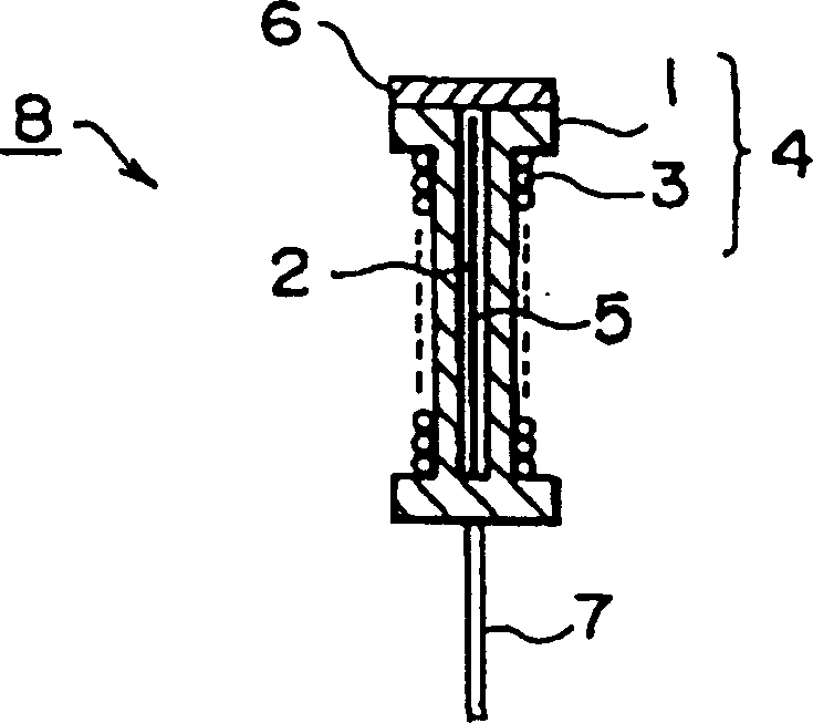
[0117] First, as Figure 4 The bobbin 10 shown has a rectangular shape with a height of 13 mm, a width of 6 mm, and a depth of 1.5 mm, and is prepared from a liquid crystal resin (liquid crystal polymer). The coil bobbin 10 has a hollow portion 11 with a rectangular section of 5×0.3 mm open at both ends. In addition, two solder-coated conductors with a square cross-section of 0.6 mm are pressed into the lower surface of the bobbin 10 as lead terminals 7 . The pitch of the lead terminals 7 is 7.62 mm so that it can be inserted into a normal circuit board.
[0118] On the above-mentioned bobbin 10, the polyurethane wires with a diameter of 0.1mm are respectively divided into 50 turns (embodiment 5), 100 turns (embodiment 6), 200 turns (embodiment 7), 100 turns (embodiment 8), 100 turns (Example 9) are wound into winding 3 . The winding length Lw of the coil 4 of Example 5 was set to 8 mm. The winding length Lw of the coil 4 of Examples 6-9 was set to 12 mm, respectively. Th...
Embodiment 10
[0129]On the same bobbin 10 as in Example 5, a polyurethane wire with a diameter of 0.1 mm was wound with 150 turns to form a winding. The winding length Lw of the coil 4 was set to 12 mm. Both ends of the winding are stripped of the coating and soldered to 2 lead terminals respectively. Next, a Co-based amorphous alloy thin ribbon having a thickness of 18 μm, a width of 4.5 mm, and a length of 26 mm was prepared as a magnetic thin ribbon, and used as a single layer. This Co-based amorphous alloy ribbon was inserted through the hollow portion, formed into a ring shape, and both ends of the alloy ribbon were laminated, and the laminated portion was fixed with an adhesive tape. Then, move the connection part into the hollow part of the bobbin.
[0130] In sample 1, the length of the connecting portion (the length of the overlapping portion) Lg was set to 4 mm, and the average magnetic path length Lc was set to 27 mm. The length Lg of this connecting portion is 15% of the aver...
PUM
| Property | Measurement | Unit |
|---|---|---|
| thickness | aaaaa | aaaaa |
| width | aaaaa | aaaaa |
| thickness | aaaaa | aaaaa |
Abstract
Description
Claims
Application Information