Transmission treatment method of optical fiber repeater and variable-channel transmission optical fiber repeater

A technology of optical fiber repeater and channel transmission, which is applied in the direction of transmission system, electromagnetic wave transmission system, electromagnetic repeater, etc., and can solve the problems of inability to install relay equipment, inconsistent network planning of wireless communication systems, base station locations, and length of optical transmission routes Inconsistent user distribution, isolation between systems, etc.

Inactive Publication Date: 2010-06-09
SHENZHEN ATUE TECH CO LTD
View PDF0 Cites 8 Cited by
  • Summary
  • Abstract
  • Description
  • Claims
  • Application Information

AI Technical Summary

Problems solved by technology

[0002] In the current wireless system, there are many kinds of wireless communication systems, such as GSM, CDAM, WCDMA, TD-SCDAM, CDMA2000 and other wireless communication systems. In the existing technology, there are dedicated optical fibers for the above wireless communication systems. The repeater is used as a relay device, but due to some special areas and tunnels, due to the limitations of the antenna installation space and the number of optical fibers brought about by its location and building boundaries, the network planning of each wireless co

Method used


Image

  • Transmission treatment method of optical fiber repeater and variable-channel transmission optical fiber repeater
  • Transmission treatment method of optical fiber repeater and variable-channel transmission optical fiber repeater
  • Transmission treatment method of optical fiber repeater and variable-channel transmission optical fiber repeater

Examples


Embodiment Construction

[0014] Embodiments of the present invention are described below by taking the accompanying drawings as examples.

[0015] Figure 1 to Figure 3 The same number in the corresponding device and module has the same name and function.

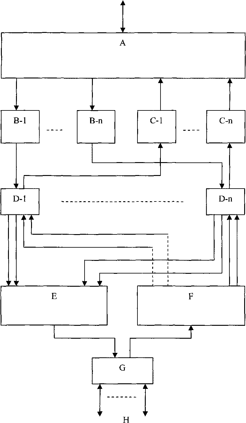
[0016] figure 1 It is an optical fiber repeater transmission processing method and a channel-changing transmission type optical fiber repeater overall electrical schematic diagram of an embodiment of the present invention, wherein: A is a wireless signal splitter and combiner, B-1~B-n are wireless receivers, and C -1~C-n are wireless transmitters, D-1~D-n are optical transmission signal adapters, E is a wavelength division multiplexer with photoelectric conversion, F is a wavelength division multiplexer with photoelectric conversion, G is optical transmission interface, H is the external optical fiber.

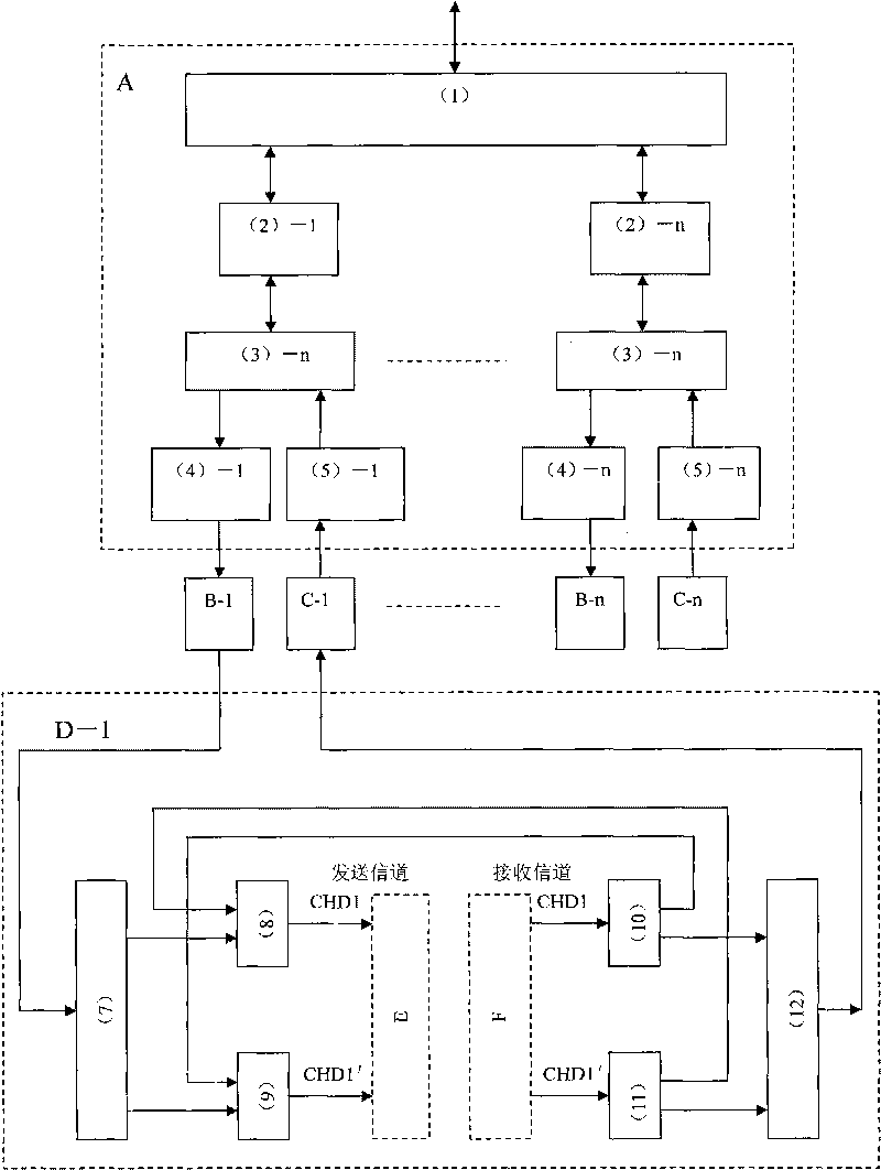
[0017] figure 2 It is a detailed electrical schematic diagram of the optical fiber repeater transmission processing method and the channel-ch...


PUM


Abstract

The invention discloses a transmission treatment method of an optical fiber repeater and a variable-channel transmission optical fiber repeater, wherein the repeater comprises the modules of a power supply, a microprocessor, an antenna feeder system, a plurality of radio receivers, a plurality of radio transmitters, optical fibers, a wavelength division multiplexer, a wavelength decomposition multiplexer, a radio signal division mixer, an optical transmission signal adaptor, an optical transmission interface and the like. The invention is capable of providing radio communication relay transmission service for all radio communication system users in special regions and tunnels, meets the requirements of reducing the number of antennas, reducing the number of the used optical fibers, reducing mutual interference among systems and meeting the insulation among the systems, is capable of realizing long-distance optical transmission relay among the optical fiber repeaters when the optical fibers are cascaded to the optical fiber repeaters, and has the characteristics of being applicable to a plurality of radio communication systems for relay transmission.

Description

technical field [0001] The invention is a wireless communication relay transmission technology, which is suitable for relay transmission of a wireless communication system in a weak field section, and belongs to the technical field of wireless communication. Background technique [0002] In the current wireless system, there are many kinds of wireless communication systems, such as GSM, CDAM, WCDMA, TD-SCDAM, CDMA2000 and other wireless communication systems. In the existing technology, there are dedicated optical fibers for the above wireless communication systems. The repeater is used as a relay device, but due to some special areas and tunnels, due to the limitations of the antenna installation space and the number of optical fibers brought about by its location and building boundaries, the network planning of each wireless communication system is inconsistent, and the network planning of each system is inconsistent. Influenced by factors such as base station location, op...

Claims


Application Information

Patent Timeline
IPC IPC(8): H04B10/16H04J14/02H04B10/29
Inventor 耿直
Owner SHENZHEN ATUE TECH CO LTD
Why Eureka
Try Eureka