Device and method for controlling waste gas
An exhaust gas and coating technology, applied in separation methods, chemical instruments and methods, dispersed particle separation, etc., can solve the problems of inoperable coating exhaust gas treatment system, heavy operation and maintenance workload, consumption of high-altitude ozone layer, etc., to reduce parking Maintenance time, manpower and material consumption, reliable operation, and low system resistance
- Summary
- Abstract
- Description
- Claims
- Application Information
AI Technical Summary
Problems solved by technology
Method used
Image

Examples
Embodiment 1
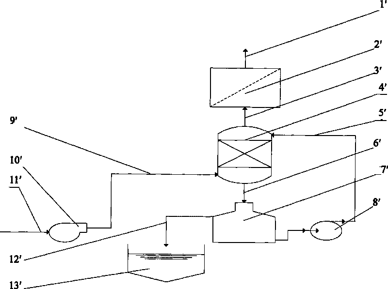
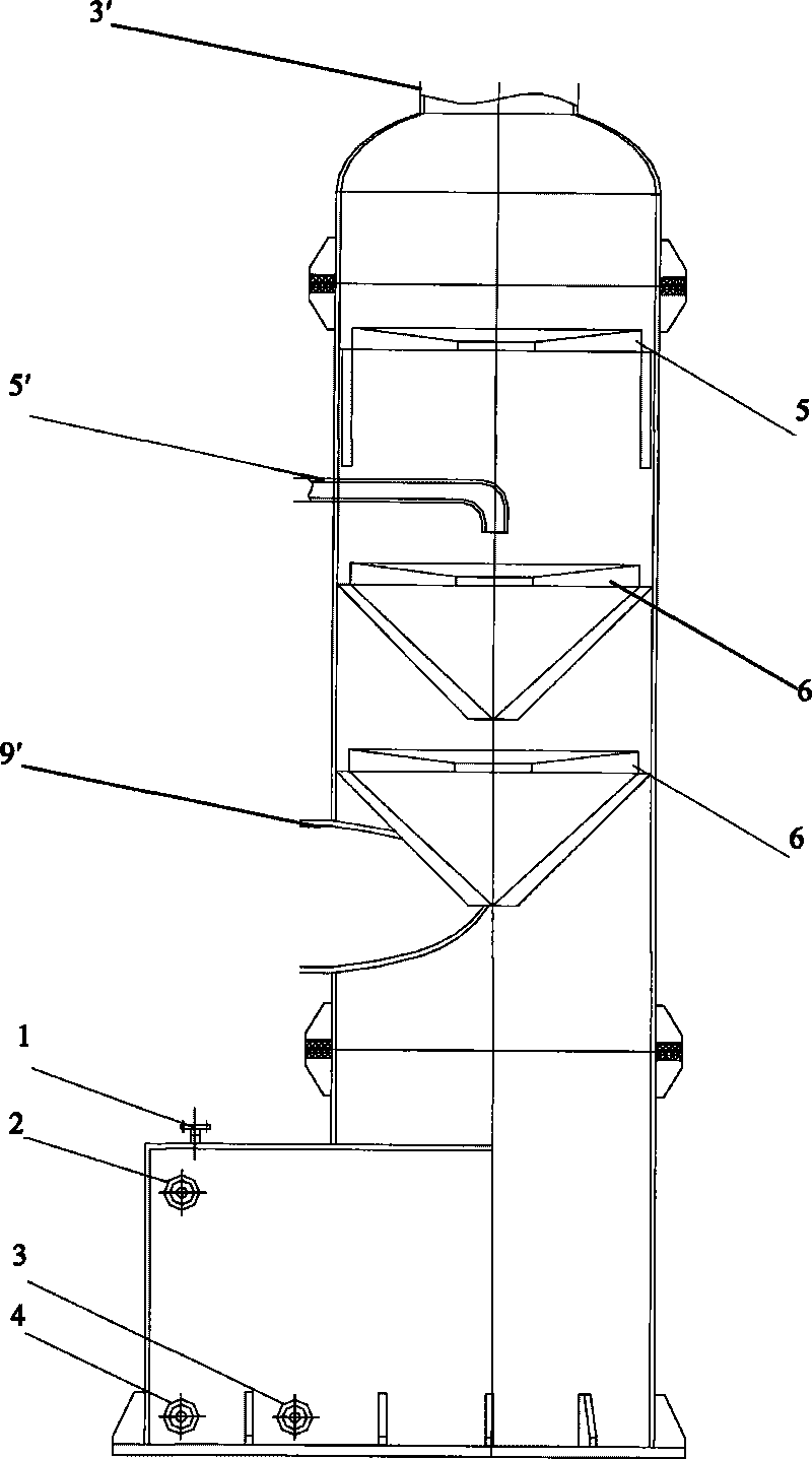
[0047] The device for controlling coating waste gas provided by this embodiment includes an adsorption liquid circulation tank 7', a swirl absorption tower 4' connected to the top of the adsorption liquid circulation tank 7' through a pipeline, and one end connected to the swirl absorption The top of the tower 4' is connected to the adsorber 2' whose other end is connected to the liquid discharge port 1'; The defogging swirl blade group 5 near the air outlet pipe 3' and the gas-liquid mixing swirl blade group 6 arranged at the top and the defogging blade group 5 pass through the side wall of the swirl absorption tower 4' The liquid inlet pipe 5' connected to the adsorption liquid circulation tank 7'; the upper and lower ends of the swirl absorption tower 4' are respectively provided with an inlet pipe 9 communicating with the gas-liquid mixing swirl blade group 6 located at the bottom ' and the gas outlet pipeline 3' communicated with the adsorber. In this device, the gas-liq...
Embodiment 2
[0052] The device for controlling coating waste gas provided by this embodiment includes an adsorption liquid circulation tank 7', a swirl absorption tower 4' connected to the top of the adsorption liquid circulation tank 7' through a pipeline, and one end connected to the swirl absorption The top of the tower 4' is connected to the adsorber 2' whose other end is connected to the liquid discharge port 1'; The defogging swirl blade group 5 near the air outlet pipe 3' and the gas-liquid mixing swirl blade group 6 arranged at the top and the defogging blade group 5 pass through the side wall of the swirl absorption tower 4' The liquid inlet pipe 5' connected to the adsorption liquid circulation tank 7'; the upper and lower ends of the swirl absorption tower 4' are respectively provided with an inlet pipe 9 communicating with the gas-liquid mixing swirl blade group 6 located at the bottom ' and the gas outlet pipeline 3' communicated with the adsorber. In this device, the gas-liq...
Embodiment 3
[0057] The device for controlling coating waste gas provided by this embodiment includes an adsorption liquid circulation tank 7', a swirl absorption tower 4' connected to the top of the adsorption liquid circulation tank 7' through a pipeline, and one end connected to the swirl absorption The top of the tower 4' is connected to the adsorber 2' whose other end is connected to the liquid discharge port 1'; The defogging swirl blade group 5 near the air outlet pipe 3' and the gas-liquid mixing swirl blade group 6 arranged at the top and the defogging blade group 5 pass through the side wall of the swirl absorption tower 4' The liquid inlet pipe 5' connected to the adsorption liquid circulation tank 7'; the upper and lower ends of the swirl absorption tower 4' are respectively provided with an inlet pipe 9 communicating with the gas-liquid mixing swirl blade group 6 located at the bottom ' and the gas outlet pipeline 3' communicated with the adsorber. In this device, the gas-liq...
PUM
 Abstract
Description
Claims
Application Information
 - R&D
- Intellectual Property
- Life Sciences
- Materials
- Tech Scout
- Unparalleled Data Quality
- Higher Quality Content
- 60% Fewer Hallucinations
Browse by: Latest US Patents, China's latest patents, Technical Efficacy Thesaurus, Application Domain, Technology Topic, Popular Technical Reports.
© 2025 PatSnap. All rights reserved.Legal|Privacy policy|Modern Slavery Act Transparency Statement|Sitemap|About US| Contact US: help@patsnap.com