Spiral bevel gear cutting machine tool and gear cutting method

A technology of spiral bevel gears and bevel gears, applied in the direction of belts/chains/gears, gear teeth, mechanical equipment, etc., can solve problems such as unstable instantaneous speed ratio, non-interchangeable processed gears, and sensitive contact areas

Inactive Publication Date: 2010-06-16
JILIN UNIV
View PDF0 Cites 30 Cited by
  • Summary
  • Abstract
  • Description
  • Claims
  • Application Information

AI Technical Summary

Problems solved by technology

The spiral bevel gears cut by the current gear cutting method are mainly spiral bevel gears. Because it is difficult to obtain spherical involute tooth profile, the tooth profile belongs to local point contact and approximate conjugate, and

Method used


Image

  • Spiral bevel gear cutting machine tool and gear cutting method
  • Spiral bevel gear cutting machine tool and gear cutting method
  • Spiral bevel gear cutting machine tool and gear cutting method

Examples


Embodiment

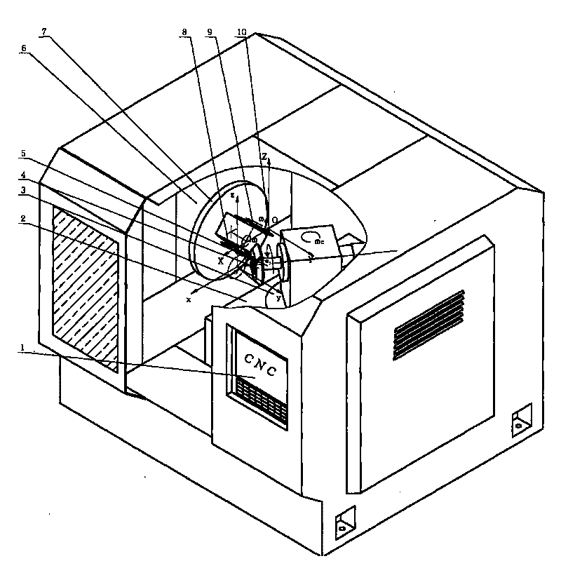
[0379] The gear cutting method of the present invention will be further described in detail through examples below. Using the spiral bevel gear cutting machine tool described in the present invention, take milling and processing spherical involute helical bevel gears as an example. For the convenience of analyzing the problem, the tooth surface of the gear is defined as follows (see Figure 5 ): When the axis of the helical bevel gear is horizontal, viewed from the small end of the helical bevel gear along the axial direction, the teeth of the helical bevel gear face upward, and the left side of the teeth of the helical bevel gear is defined as the left side, and the helical bevel gear is defined as the left side. The right side of the teeth of the gear is defined as the right side. see figure 2 , establish the rectangular coordinate system o-xzy, which coincides with the relative coordinate system of the spiral bevel gear cutting machine tool mentioned above. Among them, ...


PUM


Abstract

The invention discloses a spiral bevel gear cutting machine tool and a gear cutting method. The gear cutting machine tool comprises a cutting tool system, a workpiece system, a machine tool body and a numerical control system, wherein the cutting tool system comprises an XZ working table, an X-axis lead screw, a Z-axis lead screw, a short shaft, a tool base revolving drum, a tool base, No.1 milling cutters, a milling cutter shaft, No.2 milling cutters, a gear shaft and a correcting wedge. The rotating centre line of the tool base revolving drum and the rotating centre line of the short shaft are collinear; the right end surface of the tool base revolving drum is fixedly connected with an annular flange plate at the left end of the tool base by the correcting wedge; the right end of the tool base is provided with the milling cutter shaft; the rotating centre line of the milling cutter shaft and the rotating centre line of the short shaft are intersectant; and both ends of the milling cutter shaft are provided with the No.1 milling cutters, the No.2 milling cutters or grinding wheels. The left end surface of the tool base is provided with a drive motor; the drive motor is meshed with a bevel gear on the milling cutter shaft by the gear shaft; and the rotating centre line of the output shaft of the drive motor and the rotating centre line of the milling cutter shaft are vertically intersectant. The invention also provides a method for processing helical bevel gears by utilizing the machine tool.

Description

technical field [0001] The present invention relates to a kind of bevel gear cutting processing equipment and cutting processing method, more specifically, it relates to a kind of spiral bevel gear gear cutting machine tool and helical bevel gear gear cutting method. Background technique [0002] Gear is an important mechanical basic part of modern industry. A wide variety of gear processing machine tools are usually dedicated, such as gear hobbing machines for cutting cylindrical gears and worm gears, and bevel gear machines for cutting bevel gears. Among them, the complex gear processing machine tools and processing technologies represented by spiral bevel gears are the most complex. Spiral bevel gears are important transmission parts that transmit the motion and power of intersecting shafts. The spiral bevel gears cut by the current gear cutting method are mainly spiral bevel gears. Because it is difficult to obtain spherical involute tooth profile, the tooth profile bel...

Claims


Application Information

Patent Timeline
IPC IPC(8): B23F9/08
Inventor 张学成杨兆军彭福华蔡森叶呼咏
Owner JILIN UNIV
Why Eureka
Try Eureka