Welding wire sending and pulverized solder sending laser cladding forming method and device

A technology of laser cladding and wire feeding, which is applied in the directions of jetting device, laser welding equipment, liquid jetting device, etc., can solve the problems of the influence of scanning direction, the unreasonable feeding trajectory of powder and wire, and the quality of molten layer, etc. The effect of improving physical thermal coupling effect, ensuring optical powder air coupling, and improving optical powder coupling accuracy

Inactive Publication Date: 2010-06-16
SUZHOU UNIV
View PDF2 Cites 62 Cited by
  • Summary
  • Abstract
  • Description
  • Claims
  • Application Information

AI Technical Summary

Problems solved by technology

[0005] (1) Energy distribution is unreasonable
Since the spot is a focused solid spot, the temperature in the middle of the molten pool is high, and the temperature and tension difference between the center and the edge of the molten pool are large, resulting in strong convection of the melt in the molten pool, and the surface of the solidified molten layer is relatively uneven; moreover, when scanning The upper and middle part along the scanning line width has a long irradiation time and absorbs more energy, while the scanning irradiation time on both sides is short and absorbs less energy. Defects such as impermeability and cracks appear at the overlap between the molten layer and the adjacent layer and the lower layer.
Especially for the wire feeding process, the side wire feeding method causes the wire material to be irradiated by laser on one side, resulting in uneven heating of the material, increased power consumption and decreased quality of the molten layer
[0006] (2) The feeding track of powder and silk is unreasonable
The remaining powder that does not enter the molten pool splashes and pollutes the environment, and part of the remaining powder that is sprayed around the moving molten pool will bond, causing physical defects and roughness of the solidified surface to increase
Similarly, when the wire is fed, it must overlap with the workpiece surface and the position of the beam molten pool, and the intersection point should be limited to a small area above and below the surface of the molten pool. However, if the intersection point is opposite to the processing surface (or When there are fluctuations and changes in the upper and lower positions of the molten pool, the thermal effect of the wire will change again, which may cause the melting process of the wire to proceed intermittently, the front section of the wire is bent, and the light and wire are intermittently aligned and dislocated, so that the melt The continuity of the coating process and the quality of the melt path are very sensitive to small changes in the relative position between the molten pool and the processing surface
[0007] (3) Influence of scanning directionality
Especially when directional changes are inevitable in cladding, that is, when the laser beam scans in different directions relative to the processing surface during processing, the beam and wire have different orientations and attitudes relative to the direction of scanning motion, and the melting and The effect of the thermal action and force action process of the molten pool will change, so that the size, shape, and surface roughness of the molten channel after solidification will change greatly, and even cause the melting process to be intermittent. Surface surfacing, especially for three-dimensional direct rapid prototyping, has a particularly prominent impact. In severe cases, it is difficult to guarantee the continuity of cladding or the quality of the molten path
[0008] In addition, in the existing vermicelli composite cladding method, the structures of the powder feeding part and the wire feeding part are separated from each other, and the alignment methods of multiple powder feeding nozzles and wire feeding nozzles need to be adjusted separately during use, which is difficult to adjust

Method used


Image

  • Welding wire sending and pulverized solder sending laser cladding forming method and device
  • Welding wire sending and pulverized solder sending laser cladding forming method and device
  • Welding wire sending and pulverized solder sending laser cladding forming method and device

Examples


Embodiment 1

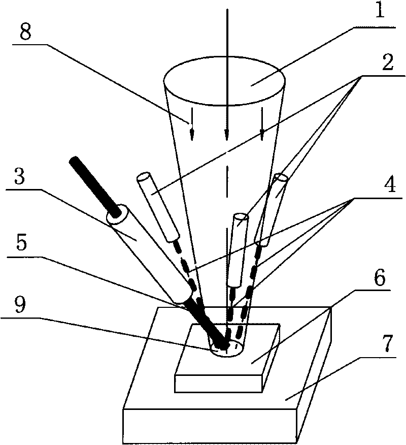
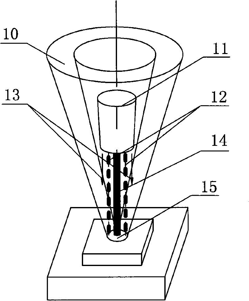
[0028] Embodiment one: see figure 2 As shown, a wire-feeding and powder-feeding composite laser cladding forming method uses a conical mirror to convert the solid laser beam emitted by the laser into a ring beam through optical path conversion, and then uses a ring focus lens to focus into a ring-shaped beam. A cone-shaped hollow light-free area is formed in the shaped beam. The compound nozzle for powder feeding, wire feeding and protective gas is placed in the light-free area and is coaxial with the ring-shaped beam. The wire feeding hole is centered, and the parallel powder feeding holes surround the wire feeding Holes, collimation and protection air holes parallel to surround the powder feeding hole, the wire material is sent into the melting pool through the wire feeding hole and the beam coaxially perpendicular to the processing surface, the airborne powder is synchronously sent into the melting pool through the powder feeding hole, and the collimation protection gas sur...


PUM


Abstract

The invention discloses a welding wire sending and pulverized solder sending laser cladding forming method. The method is characterized in that a conscope is used to change a solid laser beam transmitted by a laser to an annular light beam through light path transformation, then an annular focus lens is used to focus the annular light beam to an annular conical light beam, a hollow conical aphotic zone is formed in the annular conical light beam, a welding wire sending and pulverized solder sending protective gas composite nozzle is arranged in the aphotic zone and has the same axis of the annular conical light beam, a welding wire sending hole is arranged in the center, parallel pulverized solder sending holes are around the welding wire sending hole, collimating protective gas holes are parallel to and around the pulverized solder sending holes, wire is sent to a molten pool through the welding wire sending hole along the axial direction of the light beam and vertically to a machining face, airborne pulverized solder is sent to the molten pool through the pulverized solder sending holes at the same time, and collimating protective gas surrounds the welding wire and pulverized solder and is blown to the molten pool. The invention adopts the welding wire sending and pulverized solder sending protective gas composite nozzle to realize welding wire, pulverized solder and protective gas composite cladding and solve the defects of the prior art.

Description

technical field [0001] The invention relates to the field of laser processing, in particular to a wire-feeding powder-feeding composite laser cladding forming method and device. Background technique [0002] In the high-energy beam laser cladding manufacturing technology, there is a key technology, that is, the laser and metal materials are transmitted to the processing and forming position synchronously, and the metal materials are continuously, accurately and uniformly put into the processing surface to focus on the scanning movement according to the predetermined trajectory. In the light spot, the precise coupling of optical materials is realized. The material converts light energy and heat energy in the focused spot, instantly melts and forms a small molten pool, and the continuously moving small molten pool continuously completes the rapid melting and solidification process of the material in the molten pool, thereby forming a continuous melting channel. [0003] At pr...

Claims


Application Information

Patent Timeline
Patent Type & Authority Applications(China)
IPC IPC(8): B23K26/14B23K26/42
CPCB05B7/228B23K26/34B23K26/1411B23K26/144B23K35/0244B23K35/0261
Inventor 石世宏傅戈雁郭开波刘嘉王永康刘小东张甲
Owner SUZHOU UNIV
Why Eureka
Try Eureka