Floating-type wave energy utilization device with strong fault tolerance and high efficiency

A wave energy, floating technology, applied in the direction of ocean energy power generation, engine components, machines/engines, etc., can solve the problems of large impact load, large size, complex machinery and power generation mechanism, etc., to achieve strong buffering capacity and strong buffering. Ability, high efficiency

Inactive Publication Date: 2010-06-16
GUANGZHOU INST OF ENERGY CONVERSION - CHINESE ACAD OF SCI
View PDF0 Cites 12 Cited by
  • Summary
  • Abstract
  • Description
  • Claims
  • Application Information

AI Technical Summary

Problems solved by technology

[0002] Today, the development of floating wave energy generation devices mainly faces the following problems: 1. Most floating wave energy generation devices have low efficiency in capturing wave energy, mainly due to wave generation, transmission and reflection caused by the movement of the device itself
The reason is that high-efficiency floating devices often require less restraint. Excessive movement in large waves may easily cause anchor chain breakage, or the range or speed of the conversion device may exceed the limit, resulting in damage
3. There are relatively moving parts in the ocean wave power generation device. These parts are large in size and require sealing, so the processing and installation accuracy is difficult to meet the requirements, and the processing cost is very high
4. The peak power of the wave is 7-10 times of the average power, and each mechanism of the device is subjected to a large impact load. If the components are rigidly connected, the impact load will greatly reduce the service life of the device
However, this device has the following disadvantages: 1. There are complex machinery and power generation mechanisms inside the duck body, which is difficult to manufacture and install, and lacks a buffer link, which is easily damaged by sudden large waves.
2. The complex machinery and power generation system inside the duck body requires a large sealing chamber, and the sealing of the device is very difficult
However, both the duck body shell and the central shaft are large components, and the high finish of the joint surface between the two will inevitably lead to huge processing costs; the small gap between the two will inevitably lead to installation difficulties
Furthermore, the shell of the duck body is a welded structure, and there must be welding deformation, aging deformation, and force deformation after operation. The small gap between the shell of the duck body and the shaft cannot be guaranteed.
This is what makes canard installations expensive and makes maintenance difficult
3. The draft of the duck body floating on the sea surface is small, and the waves may transmit from the bottom of the device, which reduces the efficiency of wave energy utilization
4. The device adopts figure 2 , image 3 The mooring system requires special seabed fixing, cable tensioning or connection of rigid articulated rods and duck bodies, which is difficult
figure 2 The device uses a tensioned cable to fix the central axis, which tends to increase the draft when the tide is high, causing angular motion to create waves; when the tide is ebb, the cable is loose, resulting in line motion to create waves, and the efficiency is reduced
image 3 The mooring system of the unit is too rigid, large waves can cause sudden loads on the unit or rigid rod hinge points, resulting in damage

Method used


Image

  • Floating-type wave energy utilization device with strong fault tolerance and high efficiency
  • Floating-type wave energy utilization device with strong fault tolerance and high efficiency
  • Floating-type wave energy utilization device with strong fault tolerance and high efficiency

Examples


Embodiment Construction

[0022] Below in conjunction with accompanying drawing and embodiment content of the present invention is described in further detail:

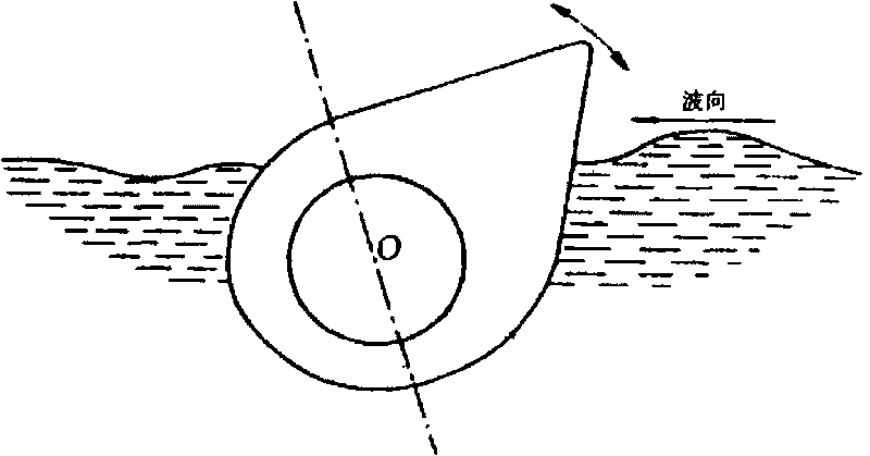
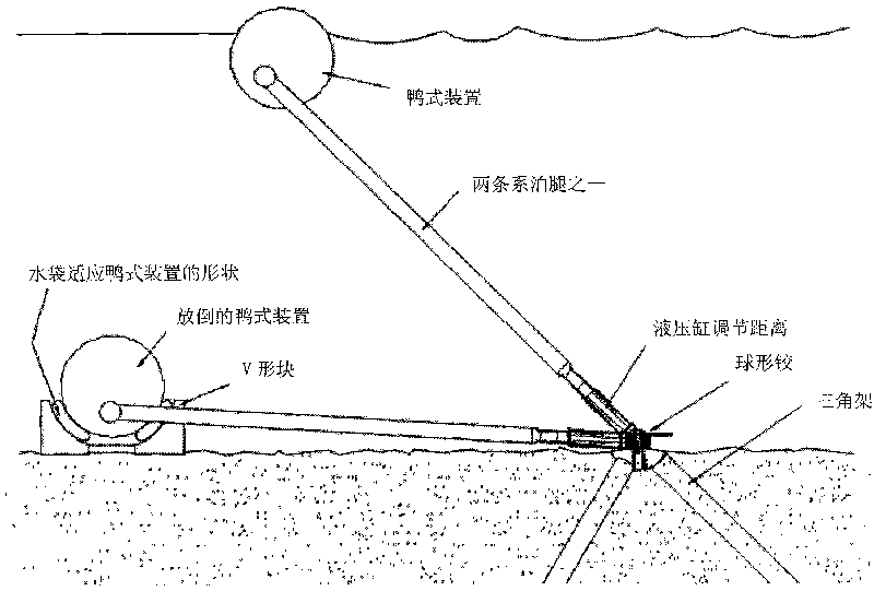
[0023] Such as Figure 4 As shown, the device of this embodiment includes a duck body 2 floating on the water surface. The duck body is composed of a head and a tail. 1 turn. The part of the central axis inside the duck body shell is a circular section, and the shaft end exposed outside the duck body shell is cylindrical, and the diameter is larger than the central axis installation hole of the duck body shell; the tail of the duck body is arc-shaped; Body head back wave position increases volume; Underwater appendage 7 fixedly connected with central axis is installed under duck body 2, and underwater appendage 7 is made up of larger horizontal plate and vertical plate. The underwater appendage 7 is hung on the shaft end of the central shaft 1, and hangs under the duck body 2. The central shaft 1 is fixed by the underwater appendage 7; The ...


PUM


Abstract

The invention provides a floating-type wave energy utilization device with strong fault tolerance and high efficiency, comprising a duck body floating on the water surface; the duck body is composed of a duck body casing and a central shaft; the duck tail is of a circular arc shape; the shaft center of the central shaft is arranged in the center of the circular arc; the part of the duck head against the wave has a larger volume; an underwater appendage which is fixedly connected with the central shaft and hangs below the duck body is installed below the duck body; a cystic pump serving as an energy switching mechanism is installed inside the duck body; the cystic pump is a closed flexible water sac which is internally injected with liquid, retained with folds and can be stretchable; the water sac is fixed on the central shaft in the duck body and the cystic pump is connected with a cystic piston through a water pipe; the upper end of the cystic piston is connected with the energy switching mechanism; the cystic pump and the cystic piston are not completely filled with liquid; and the underwater appendage is connected with the seabed through an energy storage type mooring system. The invention has low requirement on installation precision, strong fault tolerance, low cost, simple and easily realized installation and simple placement, thus being hopeful to be a floating-type wave energy generating device applied in large scale.

Description

technical field [0001] The invention relates to the technical field of wave energy utilization, in particular to an offshore floating wave energy utilization device. technical background [0002] Today, the development of floating wave energy generation devices mainly faces the following problems: 1. Most floating wave energy generation devices have low efficiency in capturing wave energy, mainly due to the wave generation, transmission and reflection of the device itself. 2. Wave devices with high conversion efficiency are difficult to survive in severe weather environments such as typhoons. The reason is that high-efficiency floating devices often require less restraint. Excessive movement in high waves may easily cause anchor chain breaks, or the range or speed of the conversion device may exceed the limit, resulting in damage. 3. There are relatively moving parts in the ocean wave power generation device. These parts are large in size and require sealing, so the process...

Claims


Application Information

Patent Timeline
Patent Type & Authority Applications(China)
IPC IPC(8): F03B13/22
CPCY02E10/38Y02E10/30
Inventor 游亚戈盛松伟吴必军
Owner GUANGZHOU INST OF ENERGY CONVERSION - CHINESE ACAD OF SCI
Why Eureka
Try Eureka