Light-gathering aiming device for tower-type solar thermal power generating system

A thermal power generation system, tower solar technology, applied in the direction of solar thermal power generation, solar thermal devices, heating devices, etc., to achieve the effect of promoting large-scale application, ingenious design, and accurate focusing

Active Publication Date: 2010-06-16
何开浩
View PDF6 Cites 15 Cited by
  • Summary
  • Abstract
  • Description
  • Claims
  • Application Information

AI Technical Summary

Problems solved by technology

[0010] The technical problem to be solved by this institute is to provide a concentrating aiming device for a tower solar thermal power generation system in view of the above-mentioned current state of the art, which overcomes the complex mathematical model and high technical requirements in the calculation of the focusing angle of the reflector by the spatial geometry method in the past , a technical problem that is difficult for large-scale industrialization

Method used


Image

  • Light-gathering aiming device for tower-type solar thermal power generating system
  • Light-gathering aiming device for tower-type solar thermal power generating system
  • Light-gathering aiming device for tower-type solar thermal power generating system

Examples


Embodiment 1

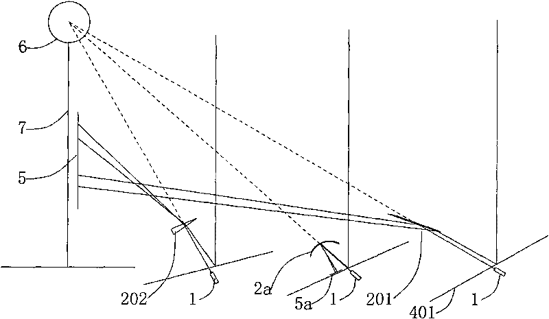
[0038] The concentrating aiming device of the tower type solar thermal power generation system in this embodiment includes a laser beam generator 1 , a light-taking projection mechanism 2 and a projection driving mechanism 3 .

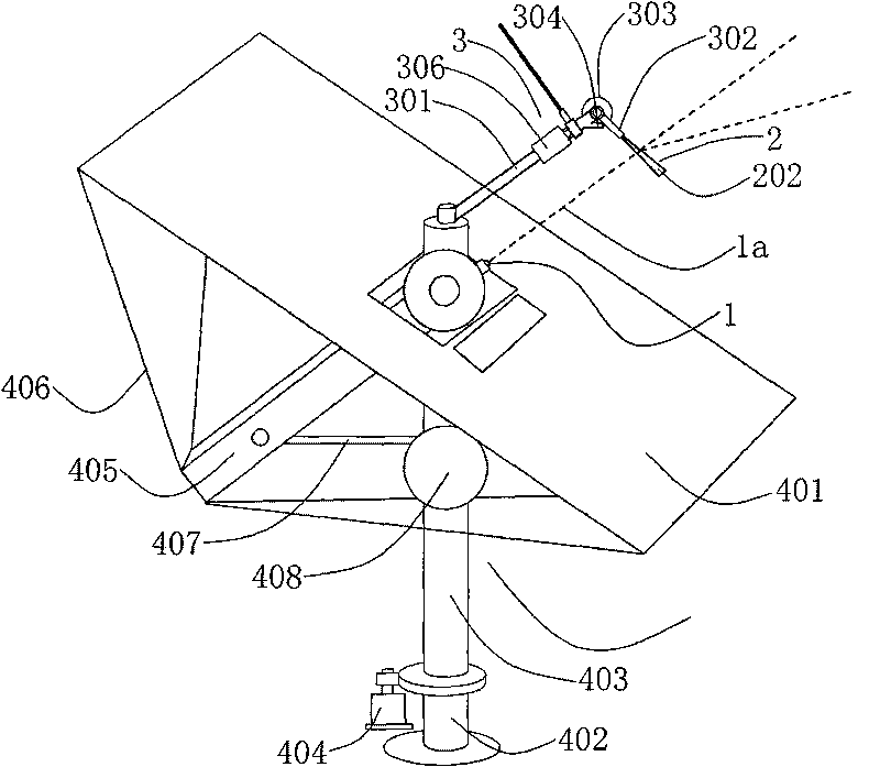
[0039] like figure 2 The single-arm solar concentrator 4 of the tower type solar thermal power generation system shown in the figure includes a base 402, a rotating drum 403 which is assembled with the base 402 and can rotate horizontally, and a third rotating drum 403 that drives the rotating drum 403. Motor 404 . A gear transmission mechanism is fixed on the power output shaft of the third motor 404 , and the rotating drum 403 is driven to rotate in the horizontal direction through the gear transmission mechanism to change the angle of the mirror 401 in the horizontal direction.

[0040] A tilting arm 405 is hinged on the upper end of the rotating drum 403 , and a reflector 401 is fixed to the free end of the tilting arm 405 through a bracket 406 ....

Embodiment 2

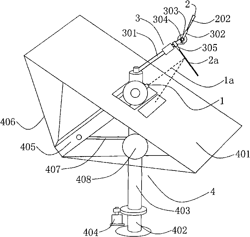
[0048] like Figure 4 The solar concentrator 4 of the tower solar thermal power generation system shown, the solar concentrator 4 includes a reflector 401 . A positioning universal joint seat 409 is arranged at the rotation center of the reflector 401 , and a positioning universal joint joint 410 a matched with the positioning universal joint seat 409 is fixedly arranged on the upper end of the positioning support rod 410 , and the reflector 401 can be freely rotated around the rotation center. . A through hole is provided at the rotation center of the reflecting mirror 401 and on the positioning universal joint seat 409, the laser beam generator 1 is arranged on the positioning universal joint joint 410a, and does not rotate with the rotation of the reflecting mirror 401, and the laser beam generator 1 1 A laser beam 1a is emitted through the through hole.

[0049] A first adjusting support rod 411 and a second adjusting support rod 413 are also provided on both sides of th...


PUM


Abstract

The invention discloses a light-gathering aiming device for a tower-type solar thermal power generating system. The device comprises laser beam generators, a light-collecting projecting mechanism and a projection driving mechanism, wherein the laser beam generators are fixedly arranged on solar light collectors around a high tower, and are positioned at the rotation centers of reflecting mirrors of the solar light collectors; the laser beam generator on each solar light collector emits laser beams aiming at a high tower solar energy stove in turn; the light-collecting projecting mechanism and the projection driving mechanism are arranged near a laser beam light path; the light-collecting projecting mechanism is a projecting reflecting mirror or a refracting mirror; while the laser beam generators are emitting laser beams, the projection driving mechanism drives the light-collecting projecting mechanism to move onto the light path of the laser beams; and the laser beams are reflected or refracted onto a light detection screen through the light-collecting projecting mechanism.

Description

technical field [0001] The invention relates to a tower-type solar thermal power generation system, in particular to a light-concentrating aiming device of the tower-type solar thermal power generation system. Background technique [0002] The solar thermal power generation system does not consume fossil energy and emit no pollutants. It is a clean energy utilization system in harmony with the ecological environment. At present, trough, tower and dish solar thermal power generation systems are also valued by countries all over the world, and work is being carried out actively. The tower system has initially shown its advantages due to its large scale, small heat loss and high temperature. [0003] The tower solar thermal power generation system is mainly composed of four parts: concentrating system, absorption and heat exchange system, heat storage system and power generation system. The concentrating system includes reflector, supporting structure, transmission device and ...

Claims


Application Information

Patent Timeline
Patent Type & Authority Applications(China)
IPC IPC(8): F03G6/06F24J2/38G02B7/198H02S20/32
CPCY02E10/46Y02E10/47Y02E10/50
Inventor 何开浩
Owner 何开浩
Why Eureka
Try Eureka