
Mobile crane, steering mid positioning and locking device and mid cylinder thereof

A locking device and oil cylinder technology, which is applied in fluid pressure actuating devices, fluid steering mechanisms, running gears, etc., can solve the problems of inability to realize automatic neutral control of steering axles, complex structure of steering locking devices, and inability to realize instantaneous automatic locking, etc. Problems, to achieve the effect of convenient wire steering and rodless steering design and layout, light weight and reliable hydraulic locking function

Active Publication Date: 2010-06-16
ZOOMLION HEAVY IND CO LTD
View PDF1 Cites 23 Cited by
  • Summary
  • Abstract
  • Description
  • Claims
  • Application Information

AI Technical Summary

Problems solved by technology

[0005] The above-mentioned steering locking device for rear axle steering of a multi-axle vehicle realizes the locked state and the unlocked state by charging compressed gas into the pneumatic cylinder and releasing the compressed gas, wherein the locked state corresponds to the road steering function controlled by the steering wheel, The unlocked state corresponds to the steering function of the rear axle controlled by the solenoid valve, which can only realize the disengagement of the steering rod system but not the automatic neutral control of the steering axle
[0006] In the process of implementing the steering neutral positioning locking device of the present invention, the inventors found that the method of charging or releasing compressed gas into the pneumatic cylinder made the steering locking device complex in structure and insensitive in response, complex in control and unable to realize instantaneous auto lock

Method used


Image

  • Mobile crane, steering mid positioning and locking device and mid cylinder thereof
  • Mobile crane, steering mid positioning and locking device and mid cylinder thereof
  • Mobile crane, steering mid positioning and locking device and mid cylinder thereof

Examples


Embodiment Construction

[0028] The embodiments of the present invention will be described in detail below with reference to the accompanying drawings, but the present invention can be implemented in many different ways defined and covered by the claims.

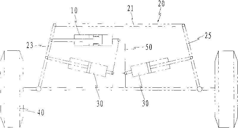
[0029] figure 1 A schematic diagram showing the installation of the middle oil cylinder on the steering axle according to the present invention is shown. As shown in Figure 1, the steering tie rod 21 and the trapezoidal arms 23, 25 form a steering trapezoid, the middle oil cylinder 10 is installed between the axle 50 and the trapezoidal arm 23, and there is also a set between the trapezoidal arms 23, 25 and the axle 50. Turn to resistance oil cylinder 30.

[0030] By setting the middle position oil cylinder 10, the steering axle can be rigidly locked in the middle position for straight driving, ensuring the high-speed running stability of the vehicle; when it is free to disengage, it is convenient for the steering axle to turn freely, realizing a s...


PUM


Abstract

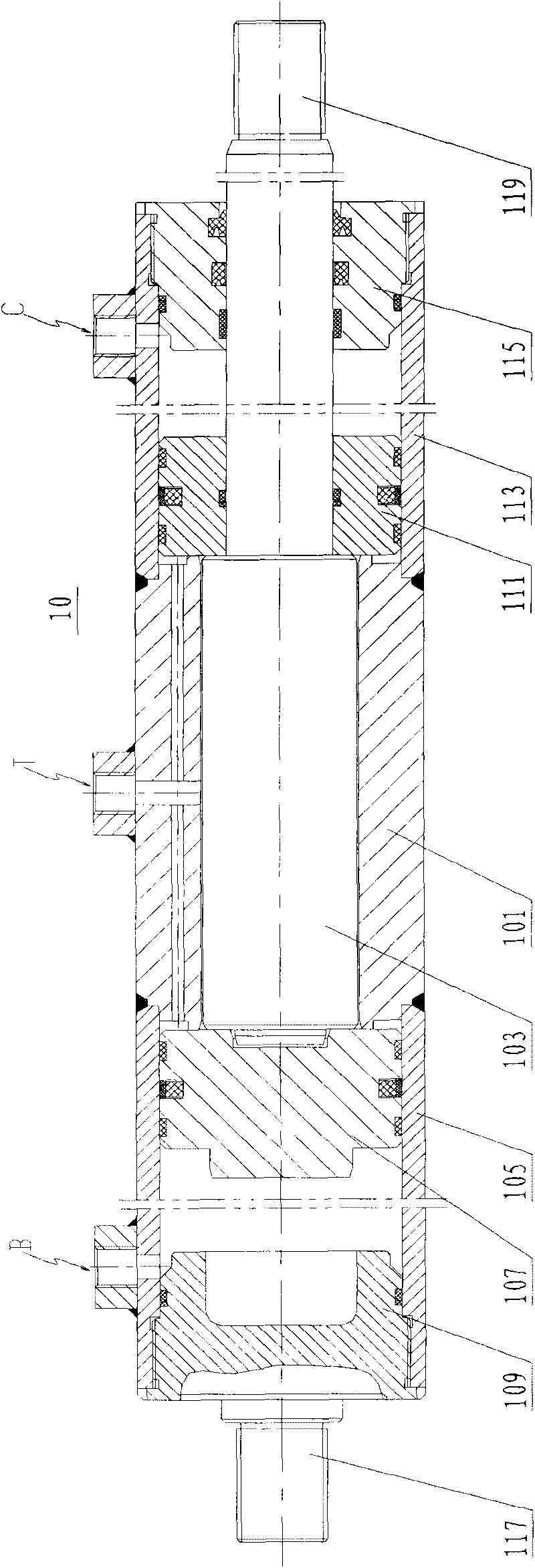
The invention discloses a mobile crane, a steering mid positioning and locking device and a mid cylinder thereof. The mid cylinder comprises a cylinder body, a first piston, a second piston, a first end cover, the second end cover and a piston rod, wherein the cylinder body comprises a middle cylinder barrel, a first cylinder barrel and a second cylinder barrel, and the first and second cylinder barrels are provided with second oil inlets that are communicated with the inner cavity, respectively; the first piston and the second piston are arranged in the first and second cylinder barrels, respectively; and the piston rod is supported in the middle cylinder barrel, penetrates through the first piston and extends out of the first end cover, and the mobile stroke of the piston rod is smaller than the length of the middle cylinder barrel. The device can realizes control of steering axle independently and locks the steering axle in the middle position to travel linearly, thereby ensuring high speed and stable traveling of a vehicle. The steering axle can steer freely when separated freely to realize smaller steering radius and greater bearing capacity of the chassis and the traveling capacity of crab walk, therefore, the large-tonnage crane tends to electrical steering, steer-by-wire and rod free steering.

Description

technical field [0001] The invention relates to a steering control of a multi-steering axle chassis used for mobile cranes such as large-tonnage or super-large-tonnage truck cranes or all-terrain cranes. Mobile crane with neutral positioning locking device. Background technique [0002] Truck cranes or all-terrain cranes that are developing towards large tonnage or super-large tonnage must have the functions of multi-axle load, multi-axle steering and various steering modes. In working conditions such as rear axle locking, how to ensure the positioning and locking of the axle steering neutral position is a necessary condition to ensure the realization of the function. [0003] At present, the center position of the crane chassis axle is mainly guaranteed by the connecting rod mechanism, which has poor safety and reliability and complicated installation arrangement, which is not conducive to the development of large-tonnage cranes towards the trend of electronically controll...

Claims


Application Information

Patent Timeline
IPC IPC(8): F15B11/028F15B13/06F15B15/02B66C9/00B62D5/12
Inventor 詹纯新刘权李义龙可游张建军李英智
Owner ZOOMLION HEAVY IND CO LTD
Learn More