High-power laser diffraction type spatial filter

A spatial filter, laser diffraction technology, applied in optics, instruments, optical components, etc., can solve the problems of two-way, two-axis spatial filtering, formation of harmful plasma, burning pinholes, etc., to improve the selection of angular spectrum performance, wide bandwidth, and improved utilization

Inactive Publication Date: 2010-06-16
谭吉春
View PDF3 Cites 16 Cited by
  • Summary
  • Abstract
  • Description
  • Claims
  • Application Information

AI Technical Summary

Problems solved by technology

When the pinhole filter is used for high-power lasers, there are the following disadvantages: the high-power laser is focused near the pinhole, the laser spot focused by the lens burns the pinhole, or forms harmful plasma in the optical path
The above patents and documents do not provide a grating filter device for the needs of multi-pass amplification and inter-stage isolation in high-power laser systems. The reported filter configuration meets the needs of single-pass filtering, but cannot meet the needs of double-pass and two-axis spatial filtering.

Method used


Image

  • High-power laser diffraction type spatial filter
  • High-power laser diffraction type spatial filter
  • High-power laser diffraction type spatial filter

Examples


Embodiment 1

[0022] Example 1: High Power Laser Diffraction Filter

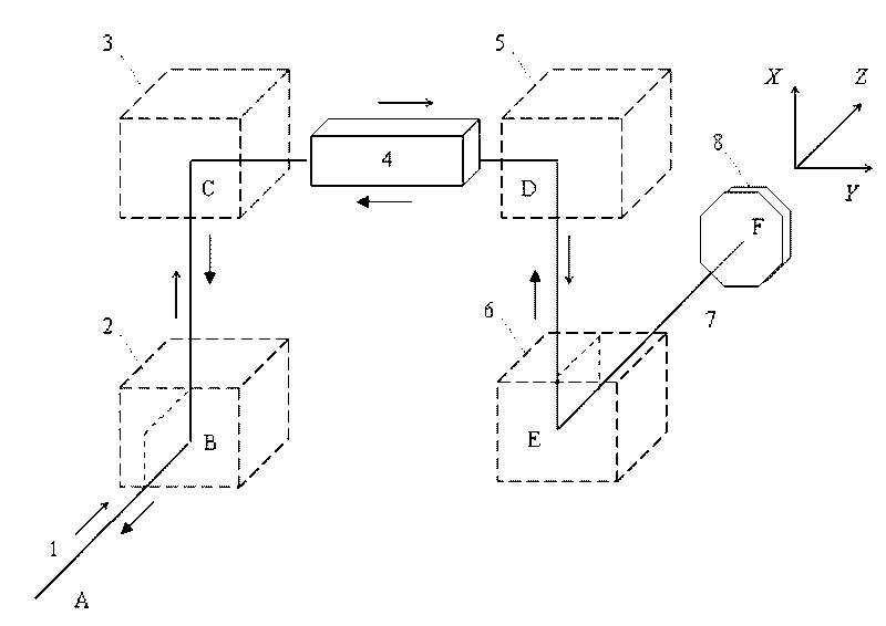
[0023] refer to figure 1 : In the filter device, on the left is an interstage isolation filter with the central axis as the vertical line BC, in the middle is a group of gain media with the central axis as the horizontal line CD, and on the right is a multi-pass cavity with the central axis as the vertical line DE For the filter, the central axis of the whole device forms a BCDEF folded line, and a separate volume Bragg grating that deflects the beam by 90° is placed at points B, C, D, and E, and a reflector is placed at point F mirror.

[0024] Among them, the interstage isolation filter is composed of two gratings (grating 2, grating 3). The multi-pass cavity filter consists of two gratings (grating 5, grating 6) and a mirror 8.

[0025] Spatial filtering using angular spectral selectivity of volume Bragg gratings. Under the action of the reflector, the laser is figure 1 The forward and reverse round trips in the d...

Embodiment 2

[0030] Embodiment 2: Class I filter composed of reflective grating

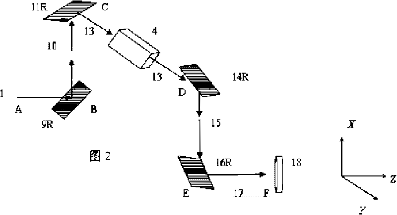
[0031] The volume Bragg grating used in this example is the "separated" grating described in claim 3, and the filtering device composed of the separated grating is called a type I device. The Class I device is characterized by figure 2 The lengths of the axes BC and DE in the center are greater than twice the cross-sectional diameter d (or side length L) of the gain medium. There is no lens in the entire optical path, and the beam has no convergence point in the filter.

[0032] The split grating used in this example is a single-period grating, and the operating state is reflective. The reflective state is characterized by the diffracted light being on the same side of the grating body as the incident light. Raster-Vector Orthogonal Two rasters are used in pairs. refer to figure 2 On the left, the interstage isolation filter consists of two volume Bragg gratings. The grating 9R is located at point B t...

Embodiment 3

[0038] Embodiment 3: Class I filter composed of a transmission grating

[0039] The volume Bragg grating used in this example is the "separated" grating described in claim 3. The split grating is a single-period grating operating in transmission mode. The characteristic of the transmission operation state is that the diffracted light and the incident light are located on different sides of the grating body. The structure of the transmissive grating type I spatial filter device is the same as that of the reflective grating device in Embodiment 2 above, and the beam propagation mode is the same.

[0040] refer to image 3 On the left, the interstage isolation filter consists of two volume Bragg gratings. The grating 9T is located at point B to deflect the beam 1 by 90° (propagating along the BC direction); the other grating 11T is located at point C to deflect the beam 10 by 90° (propagating along the CD direction). Light beam 12 leads to gain medium 4 .

[0041] refer to ...


PUM


Abstract

The invention discloses a high-power laser diffraction type spatial filter. The left side of the high-power laser diffraction type spatial filter is provided with an interstage isolation filter of which the central axis is a vertical line BC, the middle of the high-power laser diffraction type spatial filter is provided with a group of gain medium of which the central axis is a transverse line CD, the right side of the high-power laser diffraction type spatial filter is provided with a multi-pass cavity filter of which the central axis is a vertical line DE, the central axis of the entire device forms a BCDEF broken line, one optical grating which enables light beams to be deflected at 90 degrees is respectively arranged at a point B, a point C, a point D and a point E, the optical gratings are separate type volume Bragg optical gratings or double-piece integrated type optical gratings, and one reflecting mirror is arranged at a point F. The invention uses an optical grating double-pass spatial filter component which does not have a lens and a pinhole and has compact appearance to replace a pinhole filter in a multi-pass amplifier, can realize the wider width of a diffraction frequency band and can meet the requirement of short-pulse and ultrashort-pulse spatial filtering; the borne laser power is higher, and the requirement of high-power laser spatial filtering can be met, thereby eliminating the probability that laser burns out the filter component because of no lens and no pinhole in the device.

Description

technical field [0001] The invention relates to an optical space filter device, in particular to a diffraction low-pass filter device suitable for high-power laser pulses. Background technique [0002] The pinhole filter is one of the most commonly used spatial filters. It uses the Fourier transform function of the lens to separate the low-order mode and high-order mode in the incident beam on the spectrum plane, and then uses the pinhole plate (or single-mode fiber) to select the required angular spectrum components to achieve spatial low-pass filtering. When the pinhole filter is used for high-power lasers, there are the following disadvantages: the high-power laser is focused near the pinhole, the laser spot focused by the lens burns the pinhole, or forms harmful plasma in the optical path. Chinese patent 200710039731.7 discloses a confocal system composed of a quartz crystal plano-convex lens, a filter aperture, a common lens and a polarizer. The laser beam space shapin...

Claims


Application Information

Patent Timeline
Patent Type & Authority Applications(China)
IPC IPC(8): G02B27/46
Inventor 谭吉春
Owner 谭吉春
Why Eureka
Try Eureka