An anti-corrosion grounding device

A grounding device and grounding electrode technology, which is applied in the direction of connection, connection contact materials, electrical components, etc., can solve the problems of inconvenient construction, large cost of money, and easy damage to the coating film, so as to improve construction efficiency and speed and reduce construction cost. cost, the effect of increasing the equivalent diameter

Inactive Publication Date: 2012-02-15
刘义 +1
View PDF0 Cites 0 Cited by
  • Summary
  • Abstract
  • Description
  • Claims
  • Application Information

AI Technical Summary

Problems solved by technology

At present, the service life of ordinary grounding devices is at most about ten years, and it will be corroded and invalidated within 3 to 4 years. Re-excavation and laying will cost a lot of money, and will affect the safe operation of electric power and electrical devices.
In order to solve the problem of corrosion of the grounding device, various schemes have been adopted at home and abroad for many years, but the results are not ideal
If some increase the cross-sectional area of ​​the grounding device, the investment is large, and the service life will not increase for many years; some use the method of surface coating conductive paint or conductive paint. Convenience, coating quality is difficult to guarantee
If the pre-painted grounding device is used, the coating film is easily damaged due to bumps and scratches during loading, unloading, transportation and on-site construction; some use copper-clad steel materials, which are high in price and low in corrosion resistance. There are still hidden dangers, the most important is that after corrosion, it will also pollute the soil and groundwater sources
The corrosion of the grounding device is an anxious problem in the construction of the grounding network at present. If this problem is not solved properly, the life of the grounding network will be shortened, the grounding resistance will rebound, and the grounding device will even be useless. Solving the corrosion problem of the grounding device is a very urgent problem.

Method used


Image

  • An anti-corrosion grounding device
  • An anti-corrosion grounding device
  • An anti-corrosion grounding device

Examples


Embodiment Construction

[0020] In order to make it easier for those skilled in the art to understand, the present invention will be described in more detail below in conjunction with specific embodiments and accompanying drawings.

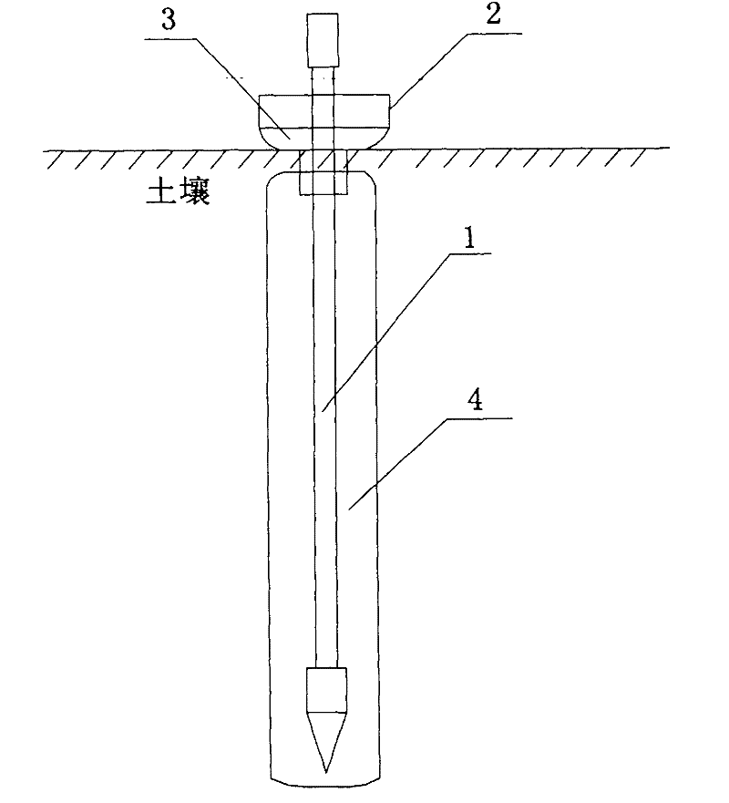
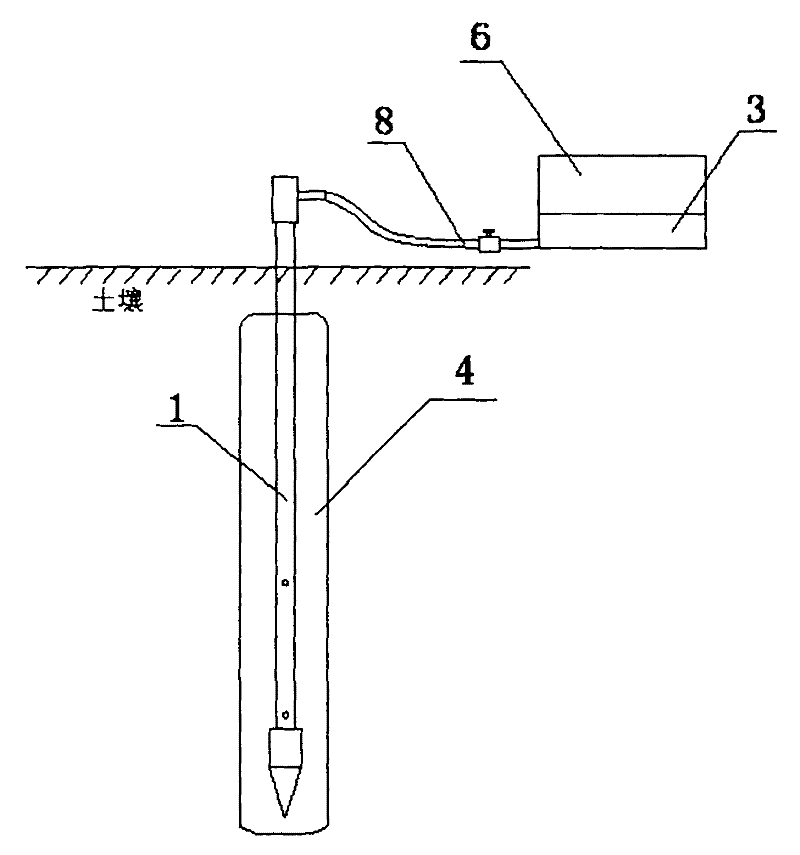
[0021] refer to figure 1 , figure 2 , an anti-corrosion grounding device, the grounding device includes a drive-in grounding electrode 1 and a potting device, as well as a protective layer 4 formed by potting slurry 3 .

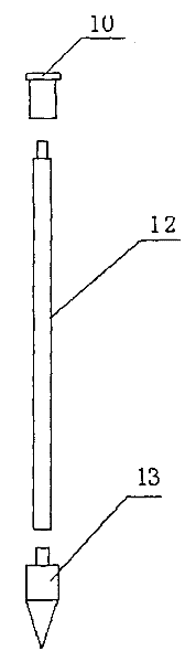
[0022] The drive-in grounding electrode 1 is composed of a striking head 10, a grounding trunk 12, and a ground-boring cone 13. The ground-boring cone 13 includes a tapered head 132 at one end and a tail 131 detachably connected to the grounding trunk. The head 132 is Cone, the tail 131 is a cylinder, and the radius of the bottom surface of the cylinder is greater than the outer diameter of the grounding trunk 12 . The potting device used in conjunction with it is composed of a potting funnel 2, a discharge hole is provided at the bottom of the funnel...


PUM


Abstract

The invention discloses an anti-corrosion grounding device, which comprises a grounding electrode and a protective layer formed by potting slurry around the grounding electrode. When in use, first bury the ground electrode underground; then create a gap between the ground electrode and the soil; finally use the potting device to pour the potting slurry into the underground gap to form a protective layer around the ground electrode. The invention greatly improves the anti-corrosion performance of the ground electrode, increases the service life, and reduces the maintenance cost of the ground grid; and the invention is extremely convenient for construction, improves the construction efficiency and speed, reduces the construction cost, and increases the conductive potting layer The equivalent diameter of the grounding electrode is increased, the combination with the soil is closer, the contact resistance is smaller, and the grounding resistance of the grounding electrode is reduced more effectively.

Description

technical field [0001] The invention relates to the field of lightning protection and safe electricity use, in particular to an anti-corrosion grounding device with convenient construction and long service life and a construction method thereof. Background technique [0002] The grounding device is an important device to ensure the safe operation of electric power and electrical systems. It faces serious corrosion problems. In addition to chemical corrosion in the soil, it is mainly electrochemical corrosion. Due to the corrosion damage of the grounding device, a large number of accidents have occurred. At present, the service life of ordinary grounding devices is at most about ten years, and it will be corroded and invalid in 3 to 4 years. Re-excavation and laying will cost a lot of money, and will affect the safe operation of electric power and electrical devices. In order to solve the problem of grounding device corrosion, various schemes have been adopted at home and abr...

Claims


Application Information

Patent Timeline
Patent Type & Authority Patents(China)
IPC IPC(8): H01R4/66H01R43/00
Inventor 王文刚
Owner 刘义
Why Eureka
Try Eureka