
Integrated Control Method of Passive Filtering and Reactive Power Compensation

A technology of comprehensive control and power compensation, applied in the direction of reactive power adjustment/elimination/compensation, reactive power compensation, harmonic reduction device, etc. Wave analysis requirements and other issues to achieve the effect of ensuring safe and reliable operation and improving production efficiency

Active Publication Date: 2012-02-01
SUZHOU POWER SUPPLY OF JIANGSU ELECTRIC POWER +1
View PDF0 Cites 2 Cited by
  • Summary
  • Abstract
  • Description
  • Claims
  • Application Information

AI Technical Summary

Problems solved by technology

[0004] Controlling branch switching according to the above compensation strategy can realize the adjustment of reactive power or even voltage, but it cannot take into account whether the harmonics meet the standards. This is mainly because the existing compensation controllers cannot meet the harmonic analysis requirements, and with the increasing With the emergence of various high-end electronic products, the problems caused by harmonics are becoming more and more serious. This application is based on the research and development of the above problems

Method used


Image

  • Integrated Control Method of Passive Filtering and Reactive Power Compensation
  • Integrated Control Method of Passive Filtering and Reactive Power Compensation
  • Integrated Control Method of Passive Filtering and Reactive Power Compensation

Examples


Embodiment Construction

[0020] The best embodiment of the present invention will be introduced below in conjunction with accompanying drawing:

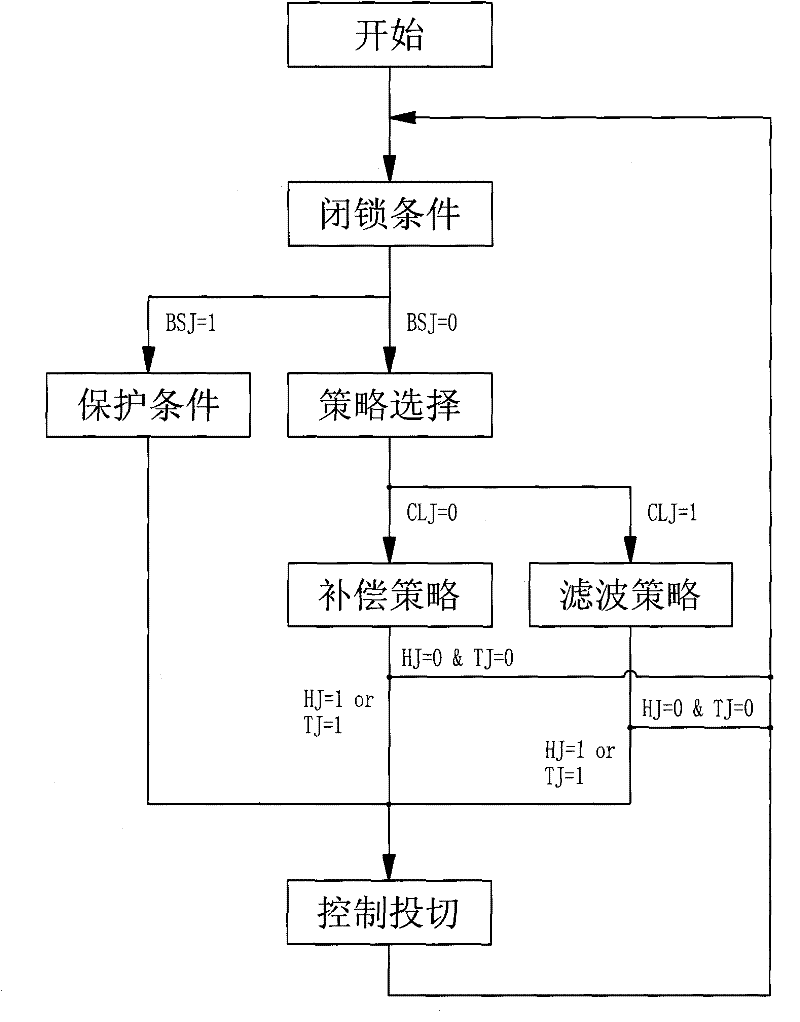
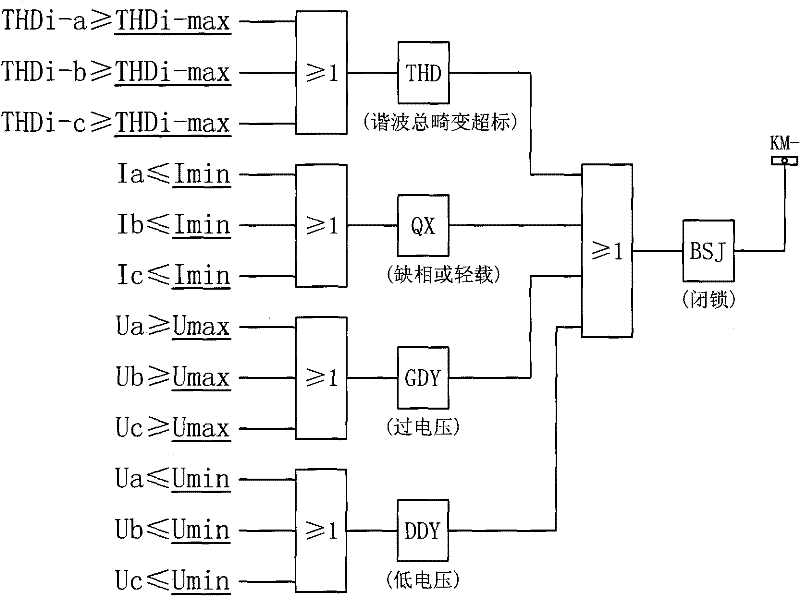
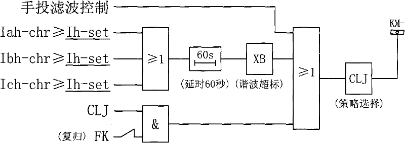
[0021] figure 1 It is the main flow chart of the passive filter and reactive power compensation comprehensive control method of the present invention. The control method is mainly realized by DSP. Before working, it is necessary to set the parameters of each system, including setting the maximum total harmonic current distortion Setting value THDi-max, minimum current setting value Imin, overvoltage setting value Umax, low voltage setting value Umin, characteristic harmonic current setting limit Ih-set, power factor setting lower limit COSΦ1, power factor setting upper limit COSΦ2, reactive power Power overcompensation tolerance limit value Qg, fundamental reactive power capacity Cp of each branch, input delay t1, cut-off delay t2, switching coefficient M, M=0~1;

[0022] After setting the above parameters, first judge the blocking conditions, which are com...


PUM


Abstract

The invention relates to a method for the comprehensive control of passive filter and reactive power compensation, which comprises: firstly, judging locking conditions including total distortion and default phase of a harmonic current and voltage threshold crossing, and locking a feed outlet and switching to a protective flow when any condition is met; and when no locking condition is met, entering a control policy selection flow, wherein the policy selection is performed mainly for judging if a potential maximum subharmonic exceeds a standard, switching is performed according to a reactive power compensation policy if the potential maximum subharmonic does not exceed the standard, and control is performed according to a filter wave if the potential maximum subharmonic exceeds the standard. In the invention, through the dual control of the reactive power compensation and the filter, a power system can output at a maximum power and the production benefits are increased; and a locking protection function is provided, so the safe and reliable operation of the system are further ensured.

Description

technical field [0001] The invention relates to a method for controlling and reactive power compensation for harmonics generated on a power supply bus in an electric power system. Background technique [0002] Due to its simple principle, convenient use and maintenance, and high cost performance compared with active filters, passive filters have become the main filtering method used in harmonic control in power systems. Passive filters use the principle of LC resonance to form a variety of filtering methods. Taking the simplest single-tuned filter as an example, it is composed of LC connected in series and tuned to the harmonic frequency that needs to be filtered out in the power grid. Since the harmonic impedance of the series LC circuit is the lowest at the tuning frequency, it behaves as a low-impedance "trap" for the sub-harmonic in the power grid, thereby absorbing the harmonic in the system. Passive filtering also has filtering methods such as second-order high-pass,...

Claims


Application Information

Patent Timeline
Patent Type & Authority Patents(China)
IPC IPC(8): H02J3/01H02J3/18
CPCY02E40/30Y02E40/40
Inventor 周文华张曦王选娇金海巍张运勇
Owner SUZHOU POWER SUPPLY OF JIANGSU ELECTRIC POWER
Learn More