Reactive power compensation and harmonic governance system and control method for realizing power compensation and harmonic governance by using the same

A technology of harmonic control and control method, applied in reactive power adjustment/elimination/compensation, AC network to reduce harmonics/ripple, harmonic reduction devices, etc., can solve the problems of waste of compensation capacity and high system cost, Achieve the effect of suppressing resonance, saving system cost and good social and economic benefits

Inactive Publication Date: 2010-06-16
哈尔滨同为电气股份有限公司 +1
View PDF4 Cites 31 Cited by
  • Summary
  • Abstract
  • Description
  • Claims
  • Application Information

AI Technical Summary

Problems solved by technology

[0008] The purpose of the present invention is to solve the problem that the existing reactive power compensation technology cannot realize the complete compensation of the power grid system while satisfying the compensation of continuously changing reactiv

Method used


Image

  • Reactive power compensation and harmonic governance system and control method for realizing power compensation and harmonic governance by using the same
  • Reactive power compensation and harmonic governance system and control method for realizing power compensation and harmonic governance by using the same
  • Reactive power compensation and harmonic governance system and control method for realizing power compensation and harmonic governance by using the same

Examples


specific Embodiment approach 1

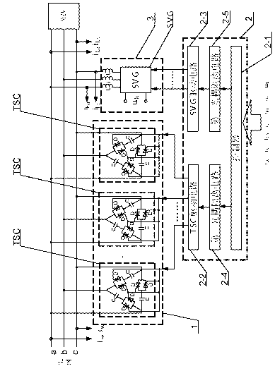
[0020] Specific implementation mode one: the following combination figure 1 , figure 2 and image 3 This embodiment will be specifically described. A reactive power compensation and harmonic control system consists of passive reactive power compensation part 1, control part 2 and active reactive power compensation and harmonic control part 3, passive reactive power compensation part 1 and active reactive power compensation and harmonic control The wave treatment part 3 is connected to the power grid in parallel,

[0021] The passive reactive power compensation part 1 is composed of M groups of thyristor switching capacitors TSC connected in parallel, the thyristor valve group composed of two anti-parallel thyristors D and the compensation capacitor C are connected in series to form a branch, and the three groups of branches A set of thyristor switching capacitors TSC is formed by connecting in a delta connection mode, and the connection points are respectively connected to...

specific Embodiment approach 2

[0026] Embodiment 2: The difference between this embodiment and the reactive power compensation and harmonic control system described in Embodiment 1 is:

[0027] said M Group thyristor switched capacitor TSC, the value of compensation capacitance C in the mth group thyristor switched capacitor TSC is determined according to the preset thyristor switched capacitor TSC compensation capacity value, wherein m is a natural number from 1 to M.

[0028] This embodiment is a further supplementary description of the capacitance value of the compensation capacitor C in the thyristor switching capacitor TSC in the first specific embodiment. The capacitance value of the compensation capacitor C is determined according to the compensation capacity of the thyristor switching capacitor TSC. pre-setting M Group thyristor switching capacitor TSC according to 2 of the unit compensation capacity n-1 Doubling the capacity compensation, using this coding method to compensate the thyristor switc...

specific Embodiment approach 3

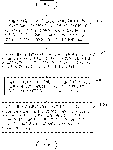
[0030] Specific implementation mode three: the following combination figure 1 , figure 2 , image 3 This embodiment will be specifically described. Applying a reactive power compensation and harmonic control system described in the first specific implementation mode to realize a control method for reactive power compensation and harmonic control, the process of reactive power compensation and harmonic control is:

[0031] Step 1. Detect the instantaneous value of phase a current of the power grid i sa and the instantaneous value of the c-phase current of the grid i sc , to detect the instantaneous value of the load phase a current i La and the instantaneous value of the load c-phase current i Lc , to detect the instantaneous value of the phase a current output by the static var generator SVG i Fa and the instantaneous value of c-phase current output by static var generator SVG i Fc , to detect the instantaneous value of the static var generator SVG DC bus voltage...


PUM


Abstract

A reactive power compensation and harmonic governance system and a control method for realizing power compensation and harmonic governance by using the same belong to the field of an electric system and solve the problems that the prior reactive power compensation technique cannot synchronously realize the full compensation for the electric network while meeting the reactive power compensation of continuous change, compensating capacity has waste and system cost is high. The system of the invention uses the structure that M groups of TSCs are connected to the electric network in parallel, the three-phase output ends of SVG are respectively connected to one end of an inductor, the other end of each of three inductors is respectively connected the three phases of the electric network. The control method of the reactive power compensation and the harmonic governance comprises: processing the collected electric current values and voltage values by a controller, obtaining the control parameters of the TSC according to a switching rule for realizing stage reactive power compensation, obtaining the control parameters of the SVG by combining with an instantaneous reactive power theory for realizing the compensation of the residual reactive power between each two stages. The invention realizes the quick and continuous reactive power compensation and the harmonic governance under the condition that load contains harmonic current, and is used for the reactive power compensation of the electric system.

Description

technical field [0001] The invention relates to a reactive power compensation and harmonic control system and a control method using the system to realize reactive power compensation and harmonic control, belonging to the field of electric power systems. Background technique [0002] In the existing power distribution system, there are many equipment with frequent and drastic changes in reactive power, such as rolling mills, injection molding machines, asynchronous motors (soft start) and port cranes, etc., which often cause problems of voltage drop and low power factor, which not only makes The line loss of the distribution network increases, and at the same time, it will cause great harm to some precision equipment with high quality requirements for power supply voltage. Therefore, the requirements for reactive power compensation devices are higher. Existing reactive power compensation devices for distribution networks mainly include passive fixed capacitors, thyristor swi...

Claims


Application Information

Patent Timeline
IPC IPC(8): H02J3/18H02J3/01
CPCY02E40/12Y02E40/10Y02E40/40
Inventor 徐殿国郭伟峰武健王立国高强
Owner 哈尔滨同为电气股份有限公司
Why Eureka
Try Eureka