Delayless control method of rotor current of grid-connection, speed-change and constant-frequency double-fed induction wind driven generator

A wind turbine, rotor current technology, applied in wind power generation, single grid parallel feeding arrangement, multi-phase network asymmetry reduction, etc., can solve the problem that the circuit cannot distinguish whether the grid voltage is balanced or unbalanced, and affects the dynamic control of the system. The performance and dynamic control effect are not ideal, to achieve the effect of improving the traversing (uninterrupted) operation ability, the control method is simple and easy to implement, and the dynamic response characteristics are good.

Inactive Publication Date: 2010-06-16
ZHEJIANG UNIV
View PDF1 Cites 23 Cited by
  • Summary
  • Abstract
  • Description
  • Claims
  • Application Information

AI Technical Summary

Problems solved by technology

In addition to the delay introduced during the separation, the bandwidth of the control system will be affected, which will cause dynamic tracking errors and the dynamic control effect is not ideal
What's more, the circuit cannot distinguish whether the grid voltage is balanced or unbalanced, and whether positive and negat

Method used


Image

  • Delayless control method of rotor current of grid-connection, speed-change and constant-frequency double-fed induction wind driven generator
  • Delayless control method of rotor current of grid-connection, speed-change and constant-frequency double-fed induction wind driven generator
  • Delayless control method of rotor current of grid-connection, speed-change and constant-frequency double-fed induction wind driven generator

Examples


Embodiment Construction

[0033] The present invention will be further described below in conjunction with the accompanying drawings and implementation examples.

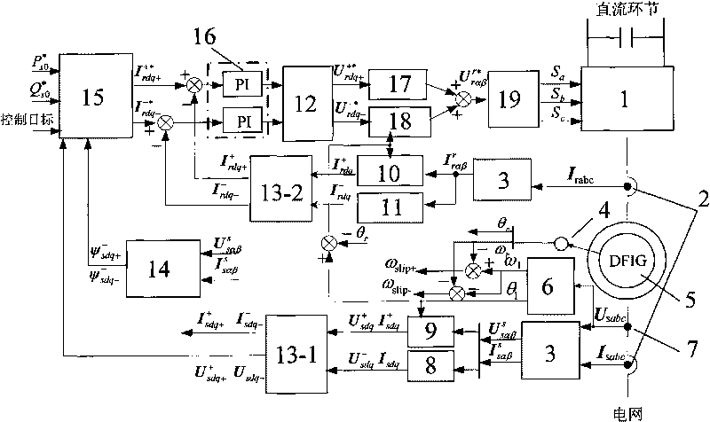
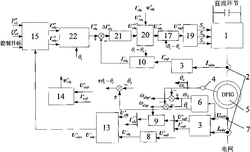
[0034] figure 2 It is a schematic diagram of the grid-connected variable-speed constant-frequency double-fed induction wind turbine rotor current control method without delay proposed by the present invention, including the control object DFIG5, and the rotor-side converter 1 (two-level or three-level) connected to the DFIG rotor level voltage type PWM inverter), Hall sensor 2 for three-phase stator and rotor current detection and Hall sensor 7 for three-phase stator voltage detection, encoder 4 for detecting DFIG rotor position and speed, and The control loop to realize the control target of DFIG under the condition of unbalanced grid voltage. The control loop is composed of a feedback signal processing channel and a forward control channel, wherein the feedback signal processing channel includes a software phase-locked loop (PLL) 6 for d...


PUM


Abstract

The invention discloses a delayless control method of rotor current of a grid-connection, speed-change and constant-frequency double-fed induction wind driven generator (DFIG). The conversion of a rotational coordinate is carried out by collecting three-phase rotor current signals, the feedback quantity of rotor current in a corotation synchronous-speed rotating coordinate system is obtained and is compared with a rotor current command in the same coordinate system, an error signal is inputted into a proportional-integral-complex coefficient resonance regulator for regulation, and the rotor reference voltage in the corotation synchronous-speed rotating coordinate system is obtained after feedback compensation decoupling and then converted into the rotor reference voltage used for space vector pulse width modulation (SVPWM) in the rotor coordinate system to generate a switching signal of a power device of a rotor side convertor so that DFIG grid-connected operation can be controlled. The method does not need to carry out positive and negative sequence decomposition of rotor current under balanced or unbalanced grid voltage, can not introduce decomposition time delay and can realize the reinforced control target of a power generation system under the unbalanced grid voltage, thereby effectively increasing the ride-through (uninterrupted) operation capability of a wind power system under power grid failure.

Description

technical field [0001] The invention relates to a control method for the rotor current of a wind power generator, especially a grid-connected variable-speed constant-frequency doubly-fed induction wind power generator suitable for grid voltage balance and unbalance (including small-value steady state and large-value transient unbalance) conditions. Generator (DFIG) rotor current without delay control method. Background technique [0002] Modern large-scale wind power generation systems mainly include double-fed induction generators (DFIG) and permanent magnet synchronous generators. In order to improve power generation efficiency, variable speed and constant frequency power generation operations are implemented, and the DFIG system is the current mainstream model. At present, my country's wind power technology mostly stays in the operation control under ideal grid conditions. Since the actual grid often has various symmetrical and asymmetrical faults, it is necessary to carr...

Claims


Application Information

Patent Timeline
IPC IPC(8): H02J3/38H02J3/26
CPCY02E10/763Y02E40/50Y02E10/76
Inventor 胡家兵贺益康
Owner ZHEJIANG UNIV
Why Eureka
Try Eureka