Device, system and method supporting base station data exchange

A technology of data exchange and base station, which is applied in the direction of data exchange network, data exchange through path configuration, digital transmission system, etc. It can solve the problems of not supporting X2 interface and achieve the effect of intercommunication

Inactive Publication Date: 2010-06-16
HUAWEI TECH CO LTD
View PDF0 Cites 15 Cited by
  • Summary
  • Abstract
  • Description
  • Claims
  • Application Information

AI Technical Summary

Problems solved by technology

[0006] When a PON network, such as GPON (or EPON) or next-generation GPON (or EPON) is used as the transmission network of the above-mentioned U-TRAN network or WiMAX network, the schematic diagram of PON-based mobile bearer is as follows figure 2 As shown, when the Optical Line Termination (OLT) receives a data packet from BS1, it can only continue to upload the data packet to the wireless gateway, and then the wireless gateway forwards the data packet to BS2, which is equivalent to the PON The network can only support the S1 interface (the interface between the BS and the wireless gateway), and cannot support the X2 interface (the interface between the BSs)

Method used


Image

  • Device, system and method supporting base station data exchange
  • Device, system and method supporting base station data exchange
  • Device, system and method supporting base station data exchange

Examples


Embodiment 1

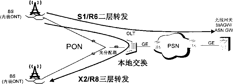
[0048] A schematic structural diagram of a PON system supporting OLT local switching provided by this embodiment is as follows image 3 shown.

[0049] exist image 3 In the PON system shown, the OLT supports data packets transmitted by the X2 / R8 and S1 / R6 interfaces, and allocates PON service logic ports for transmission by the X2 / R8 and S1 / R6 interfaces to the BS. The OLT supports Dynamic Host Configuration Protocol (Dynamic Host Configuration Protocol, DHCP) monitoring, monitors the IP address assigned to the BS through DHCP, and establishes an IP forwarding table based on the IP address of the BS and the PON service logic port, and the PON service logic port includes an input And out of the PON business logic port, so as to realize the local exchange of base station data, to support the X2 / R8 interface. In addition, the OLT adopts the Layer 2 forwarding method to support the data packets transmitted by the S1 / R6 interface, and the OLT's Layer 2 service isolation function...

Embodiment 2

[0056] For the scheme 1 in the above-mentioned implementation one, the functional structure diagram of a kind of OLT provided by this embodiment is as follows Figure 4 As shown, it includes: a PON configuration unit, an IP forwarding unit, and further includes functional units such as a network side interface processing unit, a PON interface unit, a signaling processing unit, and a MAC forwarding unit. The following describes the functions of each functional unit:

[0057] The PON interface unit is used to implement the PON interface communication function between the OLT and the BS. For GPON and its next-generation GPON, it completes the PON physical medium-related layer function in the PON protocol stack and the GPON transmission convergence layer (GPON Transmission Converge, GTC) Framing sub-layer function; for EPON and its next-generation EPON, complete EPON physical layer and data link layer functions.

[0058] The network-side interface processing unit is configured to ...

Embodiment 3

[0102] The processing flow for establishing the IP forwarding table of the X2 / R8 interface by the signaling processing unit in the second embodiment provided by this embodiment is as follows: Figure 8 As shown, the following processing steps are included:

[0103] In step 81, the OLT configures PON service logic ports (such as GEM port / LLID) used by the DHCP channels of the source BS and the destination BS respectively.

[0104] In step 82, the source BS and the destination BS perform a DHCP address allocation process with the OLT respectively.

[0105] The source BS and the destination BS request an IP address or an IPv6 address prefix from the DHCP server respectively, and the DHCP server performs a DHCP address allocation or address prefix delegation process, and assigns an IP address or an IPv6 address prefix to the source BS and the destination BS respectively. Generally, the IPv6 address prefixes assigned by the DHCP server to different BSs are also different.

[0106...


PUM


Abstract

The invention provides a device, a system and a method supporting base station data exchange. The method mainly comprises the following steps of: pre-establishing an IP forwarding table, and receiving a data message sent by a source BS; querying the IP forwarding table according to a destination IP address, an entrance physical port or an entrance ONU port and an entrance PON service logical portof the data message so as to acquire an exit physical port and an exit PON service logical port of the data message; and forwarding the data message to a destination BS by using the exit physical port or an exit ONU port and the exit PON service logical port. By using the device, the system and the method, a PON network as a transmission network supports an X2 interface, and the direct intercommunication in the true sense in stead of the intercommunication through a wireless gateway between the BSes is realized.

Description

technical field [0001] The present invention relates to the technical field of wireless communication, in particular to a device, system and method for supporting base station data exchange. Background technique [0002] The architecture diagram of the Long Term Evolution (LTE) network is as follows figure 1 As shown, the LTE network adopts a two-layer flat network structure, in which the Mobility Management Entity (MME) manages the protocols of the control plane, such as the distribution of user terminal identifiers, security, authentication, and roaming control; the Serving Gateway (Serving Gateway) , S-GW) manage user plane protocols, such as storing user terminal context, encryption context, etc. [0003] In the universal terrestrial radio access network (Universal Terrestrial Radio AccessNetwork, E-UTRAN) structure, the enhanced Node B (enhanced NodeB, eNB) uses the X2 interface to transmit handover data packets; between eNodeB and A-GW S1 interface is adopted between...

Claims


Application Information

Patent Timeline
Patent Type & Authority Applications(China)
IPC IPC(8): H04L12/56H04L12/46H04L29/06H04L29/12H04B10/272H04L45/74
CPCH04Q11/0071H04B10/272H04W92/20H04W80/04H04Q11/0067H04W8/26
Inventor 郑若滨
Owner HUAWEI TECH CO LTD
Why Eureka
Try Eureka