Hydraulic positioning mechanism

A technology of hydraulic positioning and hydraulic oil, which is applied in patient positioning for diagnosis, medical science, hospital beds, etc. It can solve the problems of safety hazards, coil heating, inconvenient clinical use, etc., and achieve the effect of convenient use and soft movements

Inactive Publication Date: 2010-06-23
北京锐致聪科技有限公司
View PDF0 Cites 3 Cited by
  • Summary
  • Abstract
  • Description
  • Claims
  • Application Information

AI Technical Summary

Problems solved by technology

There are deficiencies in these positioning methods, among which mechanical positioning such as figure 1 As shown, it is necessary to manually tighten or loosen the screws used to fix the connecting plate and the bed surface, and control the friction force of the clamp by adjusting the screws, so as to realize the fixation and movement of the bed surface relative to the bed, etc., which are very clinically used. inconvenient
The way the electromagnet pulls in is as figure 2 As shown, knocking noise and electromagnetic pulse interference will be generated when the magnet is engaged. If the magnet is in the state of energized and engaged for a long time, there will be a safety hazard of coil heating.

Method used


Image

  • Hydraulic positioning mechanism
  • Hydraulic positioning mechanism
  • Hydraulic positioning mechanism

Examples


Embodiment Construction

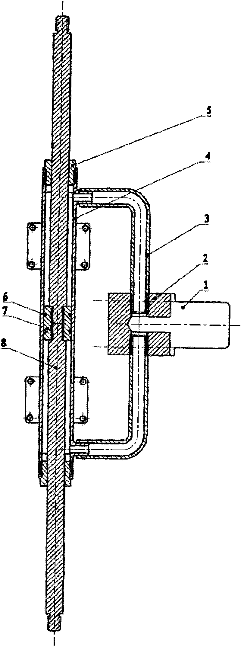
[0019] The specific embodiment is to apply the present invention to a treatment bed.

[0020] The hydraulic positioning mechanism for the treatment bed provided by this embodiment, such as image 3 As shown, the principle of incompressibility of liquid is used, the structure of double-headed oil cylinder is adopted, and a solenoid valve is used to switch the oil in and out. Its core component is a double-headed oil cylinder 4, two guide posts 8 are respectively installed on both sides of the piston 7, the piston 7 is covered with an O-ring 6 for sealing, oil nozzles are radially opened at both ends of the oil cylinder 4, through the rigid oil pipe 3 communicates with the tee 2, and the valve 1 is installed on the tee 2, and the two ends of the oil cylinder ensure the seal when the guide post 8 slides relative to the oil cylinder 4 through the head 5. When the valve is opened, push the guide post on either side to make the piston move axially relative to the cylinder, the volu...


PUM


Abstract

The invention discloses a hydraulic positioning mechanism which comprises a double-head oil cylinder and a piston thereof, and a guide column and a valve which are fixed on the piston and can slide axially relative to the oil cylinder. The closed cavity of the oil cylinder forms a hydraulic oil loop on which the valve is arranged, and when the valve is closed, the hydraulic oil loop is disconnected. When the hydraulic positioning mechanism is used, the valve is opened to enable the hydraulic oil loop in the closed cavity to be connected, external force is exerted to enable the guide column topush the piston and the oil cylinder to axially slide relatively, the distribution of the hydraulic oil in the closed cavity is changed and the hydraulic oil in the closed cavity flows from one side pressed by the piston to the other side of the closed cavity through the hydraulic oil loop. When the valve is closed, the hydraulic oil in the closed cavity stays at fixed position and due to the incompressibility of the hydraulic oil, the positions of the oil cylinder and the piston are relatively fixed, thereby reaching the purpose of positioning the guide column. The hydraulic positioning mechanism has no phenomena of energy consumption and heat radiation, is gentle in movement without causing extra noise and is safe and reliable, and convenient to use.

Description

technical field [0001] The invention relates to a positioning mechanism, in particular to a hydraulic positioning mechanism for a treatment bed. Background technique [0002] Large-scale treatment or detection equipment, such as X-ray machines, CT machines, automatic thermotherapy machines, molding machines, etc., are generally equipped with a manually adjustable movement and positioning mechanism while using a motor system for automatic motion control. In order to increase the effective range that can be treated, reduce unnecessary large-scale movement, reduce the frequency of mechanical actions that are not related to treatment or detection, and improve treatment efficiency. The positioning of the manual adjustment mechanism is mechanical, such as the FEP-BY series hyperthermia machine of Beijing Yuande Biomedical Engineering Co., Ltd.; some use electromagnet attraction, such as the F30- IIF 200mA X-ray machine. There are deficiencies in these positioning methods, among ...

Claims


Application Information

Patent Timeline
Patent Type & Authority Applications(China)
IPC IPC(8): A61G7/018A61B6/04
Inventor 于晋生李春石长亮雒自清肖灵
Owner 北京锐致聪科技有限公司
Why Eureka
Try Eureka