
Servo hydraulic-control tire formation machine

A tire building machine and hydraulic technology, applied to tires, other household appliances, household appliances, etc., can solve the problems of energy conversion not as high as hydraulic transmission, loose fastening screws of equipment, large amount of hydraulic oil, etc., and achieve high energy utilization rate , the effect of suppressing the rise of oil temperature and reducing the cost of use

Pending Publication Date: 2020-03-03
福建建阳龙翔科技开发有限公司
View PDF0 Cites 1 Cited by
  • Summary
  • Abstract
  • Description
  • Claims
  • Application Information

AI Technical Summary

Problems solved by technology

[0002] Most of the existing tire building machines are driven by motors. The noise caused by the motor drive is not as stable as that of the hydraulic transmission, and the energy conversion is not as high as the hydraulic transmission. The ordinary hydraulic transmission device, because the motor runs at the rated speed to drive the oil pump, the system The pressure is controlled by the relief valve, and the excessive pressure is relieved, which is a continuous and constant high-energy consumption operation mode. The continuous operation of the relief valve will generate oil temperature, and it is necessary to increase the cooler and use cooling water to circulate and cool down; hydraulic standby There will be a certain amount of noise, and the noise will be louder under high pressure; there will be a certain impact when the action is switched, which will loosen the fastening screws of the equipment for a long time, requiring frequent maintenance and reinforcement screws.
Due to the cooperation with oil temperature control, a large amount of hydraulic oil is required

Method used


Image

  • Servo hydraulic-control tire formation machine
  • Servo hydraulic-control tire formation machine
  • Servo hydraulic-control tire formation machine

Examples


Embodiment Construction

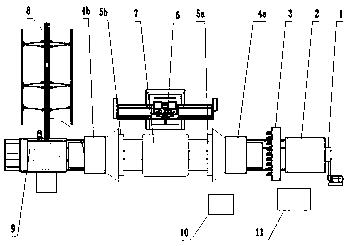
[0020] Such as figure 1 Shown: 1 folding drum device, 2 main box, 3 clamping traction device, 4a fixed end of front and back wrapping device, 4b moving end of front and back wrapping device, 5a fixed end of buckle ring, 5B moving end of buckle ring, 6 forming drum, 7 Roller device, 8 guide device, 9 rotating tailstock device, 10PLC control cabinet, 11 servo hydraulic station;

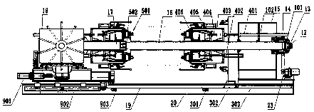
[0021] Such as figure 2 Shown: 12 rotary joint, 13 hydraulic distributor, 14 transmission disc, 15 main chassis, 401 outer sleeve oil cylinder, 402 capsule oil cylinder, 403 outer sleeve, 404 finger-shaped positive pack oil cylinder, 405 finger-shaped positive pack seat, 406 Capsule turn-up seat, 16 main shaft, 17 support shaft, 18 expansion guide shaft, 19 rotating chassis, 20 machine base, 21, transmission disc, 22 belt, 23 servo motor, 501 buckle cylinder, 502 buckle seat;

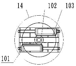
[0022] Such as image 3 Shown: 101 folding drum oil cylinder, 102 gears, 103 racks;

[0023] Such as Figure 4 Shown: 301...


PUM


Abstract

The invention relates to a servo hydraulic-control tire formation machine. The servo hydraulic-control tire formation machine is characterized in that the end of a formation machine spindle (16) is provided with a rotation connector (12) and a hydraulic distributor (13), all parts of the formation machine are subjected to servo hydraulic-control, a pressure sensor is arranged in an oil cylinder, and a servo hydraulic station (11) is controlled by a servo motor. A PLC (10) gives two paths of analog quantity 0-10V signals, one path is a pressure command, and the other path is a rotation speed command. A servo system performs closed-loop control over the pressure and rotation speed of the system through the received signals and feedback of the pressure sensor and a rotary encoder, in cooperation with a high-efficiency internal meshing gear pump, a control valve provides a power source for the oil cylinder, in cooperation with the pressure sensor arranged in the oil cylinder, the speed iscontrolled to be progressively increased or decreased when the air cylinder moves, so that all actions of overall tire formation machine equipment are soft, no impact is generated during action switching, and accordingly the service life of the machine is prolonged.

Description

technical field [0001] The invention relates to a tire building machine, in particular to an improvement of a tire building machine control device. Background technique [0002] Most of the existing tire building machines are driven by motors. The noise caused by the motor drive is not as stable as that of the hydraulic transmission, and the energy conversion is not as high as the hydraulic transmission. The ordinary hydraulic transmission device, because the motor runs at the rated speed to drive the oil pump, the system The pressure is controlled by the relief valve, and the excessive pressure is relieved, which is a continuous and constant high-energy consumption operation mode. The continuous operation of the relief valve will generate oil temperature, and it is necessary to increase the cooler and use cooling water to circulate and cool down; hydraulic standby There will be a certain amount of noise during operation, and the noise will be louder under high pressure; the...

Claims


Application Information

Patent Timeline
IPC IPC(8): B29D30/08
CPCB29D30/08
Inventor 戴造成沈国雄巫松青
Owner 福建建阳龙翔科技开发有限公司
Learn More