New high-efficiency whirling milling head

A high-efficiency whirlwind milling technology, used in thread cutting tools, metal processing equipment, tangent devices, etc., can solve problems such as the theoretical centerline and the rotation center of the whirlwind head do not coincide, affect the tooth shape accuracy and finish, and affect the whirlwind milling efficiency. , to achieve the effect of less technical difficulty in installing the knife, accurate positioning and high positioning accuracy

Inactive Publication Date: 2010-06-23
南靖长青精密丝杆制造有限公司
View PDF1 Cites 10 Cited by
  • Summary
  • Abstract
  • Description
  • Claims
  • Application Information

AI Technical Summary

Problems solved by technology

Its disadvantages: ①Using one-time milling, the tool is easy to wear, and the tool is often replaced due to unqualified thread accuracy
③These three knives should be installed on the same rotating circle tangent line, and there should be no interference between rough and fine cutting. Overcutting will affect the accuracy and smoothness of the tooth profile. This way the installation and cutting technology is difficult and the installation time is very long, which affects the cyclone milling. s efficiency
Every time the tool is reground, it is difficult to ensure that the symmetry of the tangent line in the middle of the tool and the dimensional accuracy of the tooth thickness are consistent.
④ The above three reasons will cause the theoretical center line of the tool to not coincide with the center of rotation of the cyclone head, resulting in tooth shape distortion
⑤It is very difficult to correct the tooth shape of the screw with different angles and pitches by rotary cutting according to the current technology of the cyclone head.
⑥ At present, foreign countries use non-regrinding machines to clamp blades, which will result in high tool costs

Method used


Image

  • New high-efficiency whirling milling head
  • New high-efficiency whirling milling head
  • New high-efficiency whirling milling head

Examples


Embodiment Construction

[0029] Now illustrate the present invention in conjunction with accompanying drawing and embodiment.

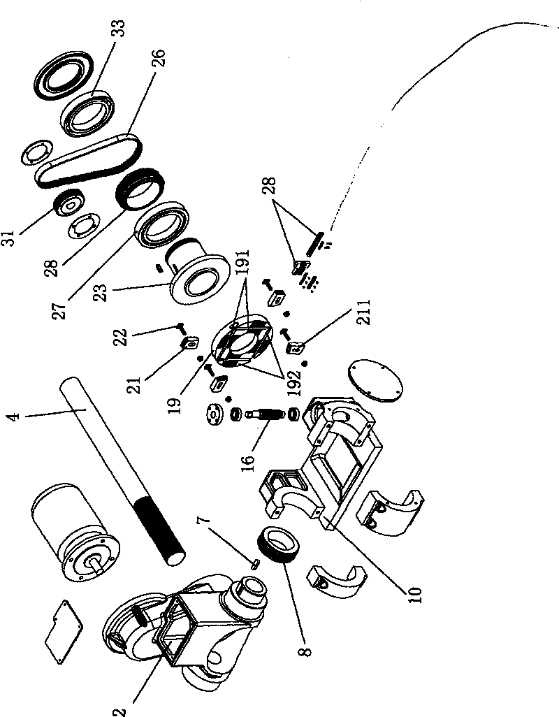
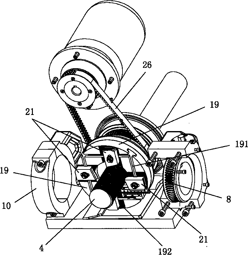
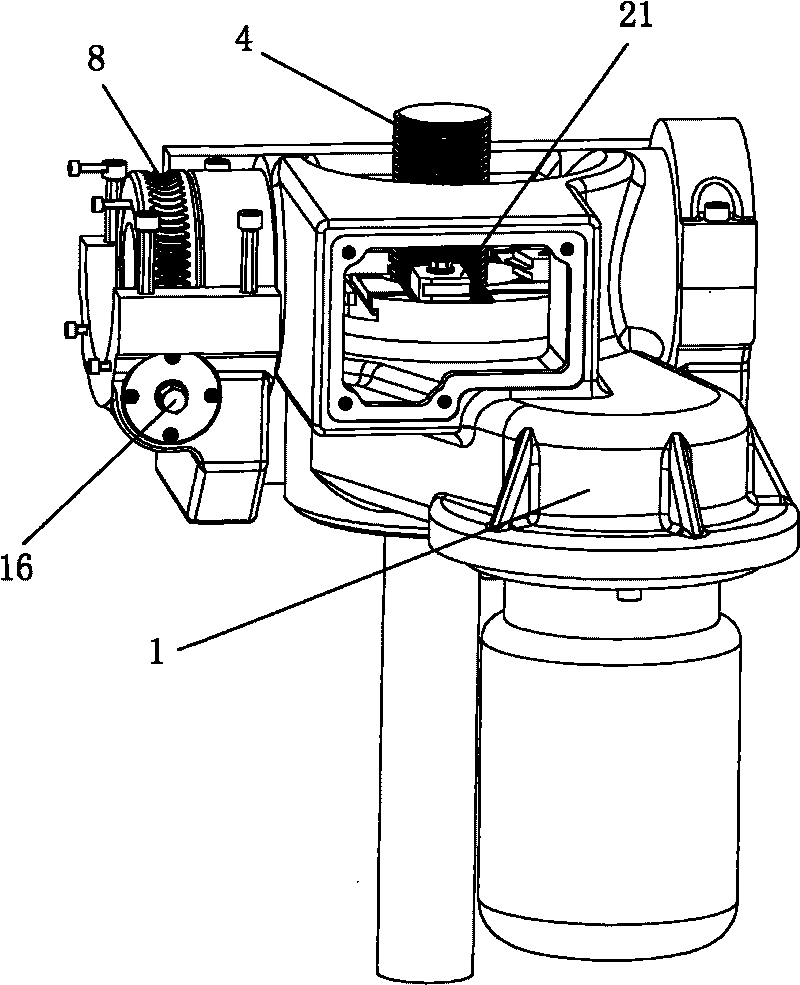
[0030] Such as figure 1 , 2 , The high-efficiency novel whirlwind milling head shown in 3, it is made up of a group of cutter bar 21, milling cutter disc 19, milling cutter disc main shaft 23 and a belt transmission mechanism. The workpiece 4 passes through the central cavity of the milling cutter head 19, and the rotation center of the milling cutter head 19 and the rotation center of the workpiece 4 maintain a certain eccentricity.

[0031] Described milling cutter disc 19: its end face is provided with four tool slots 191 arranged in a square, and the rotation center lines of the four tool slots 191 coincide with the rotation center line of the milling cutter disc 19; the end faces of the milling cutter disc 19 are also It has rattooth-shaped teeth 192, and its straight teeth are arranged perpendicular to the slotting direction of the knife groove 191.

[0032] Describe...


PUM

PropertyMeasurementUnit
lengthaaaaaaaaaa

Abstract

The invention discloses a new high-efficiency whirling milling head. Four cutter bars are fixedly arranged on four cutter installing grooves on a milling cutter disk, and the milling cutter disk is provided with mouse tooth-shaped gears meshed with the cutter bars, so that the cutter bars can be positioned more reliably and can be assembled and disassembled more conveniently. The positions of the cutter bars in the cutter installing grooves are adjusted by a vernier depth gauge to meet the condition that the center of the top edge of a cutter passes through the axle center of a workpiece. In the invention, the milling cutter disk and a pulley drive mechanism fixing cover are arranged in a whirling milling head cover body, and the lift angle of a milling head which is integrally connected with the whirling milling head cover body is adjusted through a set of screw bevel gear mechanism. After the cutter bars are worn, only the top surfaces of the obtuse parts of the cutter bars need to be ground, the tooth thickness and the cutting center line of the cutter bars can not be changed, the cutter bars can be reground for many times, and the dimensional accuracy and the positioning accuracy of the cutter bars can not be changed. The cutter which is ground by being vertically inclined for 13 degrees by the cutter bars is in a shortened tooth shape, still has very high strength and can be used for powerful high-speed milling.

Description

technical field [0001] The invention relates to the field of mechanical processing, in particular to a milling head device of a whirlwind milling screw machine tool. Background technique [0002] For the milling head device of the whirling milling screw in the prior art, please refer to the ZL200420038752.9 disclosed in the Chinese patent document on February 2, 2005. In the tool slot, the milling cutter disc is rigidly connected to the cutter shaft and connected to a belt transmission mechanism. The outer circle of one end of the cutter shaft is equipped with a bearing, the outer ring of the bearing is installed on the swing bracket, and the other end of the swing bracket is equipped with a motor, which is driven by the belt. Mechanism connection, the swing shafts at both ends of the swing support are installed on the milling cutter seat, and the swing shaft of the swing support is connected with a swing adjustment mechanism; a set of grooves on the plane of the milling cut...

Claims


Application Information

Patent Timeline
Patent Type & Authority Applications(China)
IPC IPC(8): B23G1/32B23G1/44B23G5/18
Inventor 吴伟
Owner 南靖长青精密丝杆制造有限公司
Why Eureka
Try Eureka