

Electrified railroad through power supply system without split phase
An electrified railway, split-phase connected technology, applied in power lines, transportation and packaging, vehicle components, etc., can solve problems such as speed reduction, abnormal train stop, train loss of power, etc., to reduce negative sequence and reactive power. , saving investment and operation, improving the effect of power quality
- Summary
- Abstract
- Description
- Claims
- Application Information
AI Technical Summary
Problems solved by technology
Method used
Image

Examples
Embodiment 1
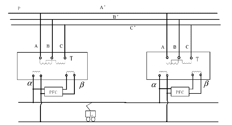
[0025] figure 1 It shows a non-phase-separated continuous power supply system for electrified railways, which is composed of: the traction transformer in the traction substation S is a three-phase-two-phase balance transformer T, and the three-phase-two-phase balance transformer T in each traction substation S The primary three-phases A, B, and C of the transformer T are connected to the three-phases A', B', and C' of the same public grid P, and the power flow controller PFC is connected to the two output phases of the three-phase-two-phase balance transformer T Between α and β, one of the two output phases α and β supplies power to the locomotive; and each traction substation S uses the same phase ( figure 1 The middle is the α phase) to supply power for the locomotive.
[0026] Figure 4 It is shown that the power flow controller PFC in this example is composed of a single-phase isolation transformer T1, a voltage source inverter NB1, a DC coupling capacitor C1, a voltage ...
Embodiment 2
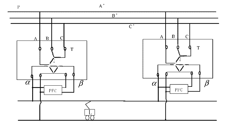
[0029] figure 2 It shows a non-phase-separated continuous power supply system for electrified railways, which is composed of: the traction transformer in the traction substation S is a three-phase-two-phase balance transformer T, and the three-phase-two-phase balance transformer T in each traction substation S The primary three-phases A, B, and C of the transformer T are connected to the three-phases A', B', and C' of the same public grid P, and the power flow controller PFC is connected to the two output phases of the three-phase-two-phase balance transformer T Between α and β, one of the two output phases α and β supplies power to the locomotive; and each traction substation S uses the same phase to supply power to the locomotive.
[0030] Figure 4 It is shown that the power flow controller PFC in this example is composed of a single-phase isolation transformer T1, a voltage source inverter NB1, a DC coupling capacitor C1, a voltage source inverter NB2 and a single-phase ...
Embodiment 3
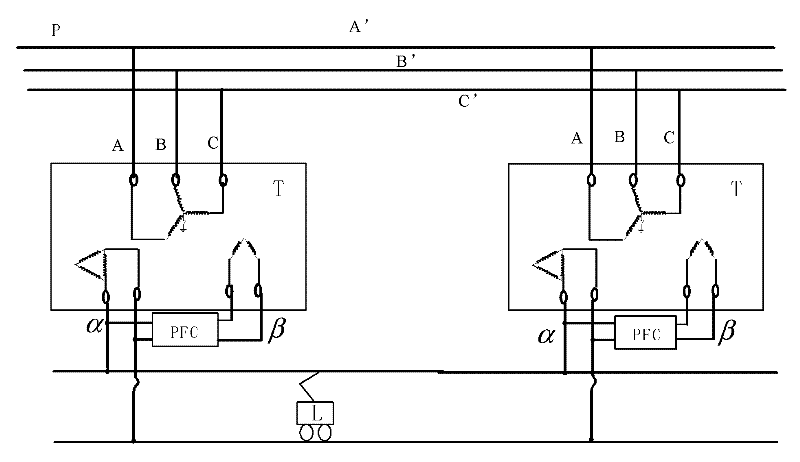
[0033] image 3 It shows a non-phase-separated continuous power supply system for electrified railways, which is composed of: the traction transformer in the traction substation S is a three-phase-two-phase balance transformer T, and the three-phase-two-phase balance transformer T in each traction substation S The primary three-phases A, B, and C of the transformer T are connected to the three-phases A', B', and C' of the same public grid P, and the power flow controller PFC is connected to the two output phases of the three-phase-two-phase balance transformer T Between α and β, one of the two output phases α and β supplies power to the locomotive; and each traction substation S uses the same phase to supply power to the locomotive.
[0034] Figure 4 It is shown that the power flow controller PFC in this example is composed of a single-phase isolation transformer T1, a voltage source inverter NB1, a DC coupling capacitor C1, a voltage source inverter NB2 and a single-phase i...
PUM
 Abstract
Description
Claims
Application Information