Scroll compressor

A technology of scroll compressors and back pressure chambers, applied in the direction of rotary piston machines, rotary piston pumps, mechanical equipment, etc., can solve the problems of increased operation rise time, increased pressing force, increased mechanical loss, etc., to achieve Effects of shortening operation rise time, reducing leakage and mechanical loss

Active Publication Date: 2010-06-23
HITACHI JOHNSON CONTROLS AIR CONDITIONING INC
View PDF2 Cites 17 Cited by
  • Summary
  • Abstract
  • Description
  • Claims
  • Application Information

AI Technical Summary

Problems solved by technology

Therefore, during low-speed operation in which the pressing force of the orbiting scroll does not need to be so large, the pressing force of the orbiting scroll increases, causing a problem that the mechanical loss between the wraps of the orbiting scroll and the fixed scroll increases.
[0008] In addition, in the scroll compressor of Patent Document 2, if it is not a high-pressure box type, there is a restriction that refrigerant gas at discharge pressure cannot be introduced into the annular back pressure chamber on the back side of the thrust ring.
In addition, in the scroll compressor of Patent Document 2, since the refrigerant gas at the discharge pressure of the internal space of the hermetic container is introduced into the annular back pressure chamber, it is necessary to start the operation until the discharge pressure of the internal space of the hermetic container rises. For a long time, there is a problem that the time until the transition to stable operation, that is, the operation rise time increases.

Method used


Image

  • Scroll compressor
  • Scroll compressor
  • Scroll compressor

Examples


Embodiment Construction

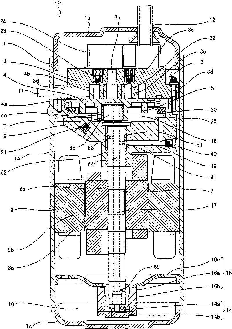
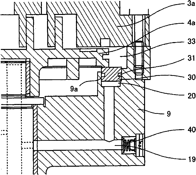
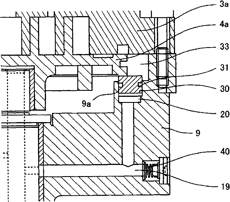
[0025] Next, use Figure 1 to Figure 6 A scroll compressor according to one embodiment of the present invention will be described. figure 1 is a longitudinal sectional view of a scroll compressor according to this embodiment, figure 2 yes figure 1 An enlarged view of the thrust ring portion when the operation of the scroll compressor is stopped, image 3 yes figure 1 An enlarged view of the thrust ring during operation of the scroll compressor, Figure 4 yes figure 1 A longitudinal sectional view of the single state of the thrust ring, Figure 5 yes figure 1 A longitudinal sectional view of the single state of the thrust ring, Figure 6 yes figure 1 An enlarged view of the intermediate pressure control valve section of the scroll compressor. The scroll compressor 50 of the present embodiment is used as a scroll compressor for refrigeration equipment, air conditioning equipment, and gas compression such as air and nitrogen.

[0026] The scroll compressor 50 is config...


PUM


Abstract

The invention discloses a scroll compressor, which can reduce the leakage between a cyclotron scroll pan and an immobile scroll pan and the mechanical loss in a larger running range, and shorten the running rise time. The scroll compressor (50) has, in a sealed container (1), a compressing mechanism part (2) with the immobile scroll pan (3) and the cyclotron scroll pan (4), and a motor to drive the cyclotron scroll pan (4) by a crankshaft (6). A thrust collar (30) is arranged at the back side of the cyclotron scroll pan (4), a circular backpressure chamber (20) is arranged at the back side of the thrust collar (30), an oil storage part (10) for storing a lubricating oil is arranged in the sealed container (1), and an oil supply mechanism for supplying the lubricating oil in the oil storage part (10) by the rotating of the crankshaft (6) is provided. The lubricating oil supplied by the oil supply mechanism is guided into the circular backpressure chamber (20) so as to press the thrust collar (30).

Description

technical field [0001] The present invention relates to a scroll compressor, especially a scroll compressor preferably used for refrigeration equipment, air conditioning equipment, and gas compression such as air and nitrogen. Background technique [0002] Conventionally, there is known a scroll compressor in which a compression mechanism unit including a fixed scroll and an orbiting scroll and an electric motor for orbitally driving the orbiting scroll are arranged inside a hermetic container. In this scroll compressor, the orbiting scroll receives a force in a direction away from the fixed scroll due to the pressure of the compression chamber, and refrigerant leakage between the fixed scroll and the orbiting scroll may increase. [0003] Therefore, in the low-pressure box-type scroll compressor, the following technology has been proposed: in order to suppress the leakage of the refrigerant between the fixed scroll and the orbiting scroll, by disposing the thrust ring on th...

Claims


Application Information

Patent Timeline
Patent Type & Authority Applications(China)
IPC IPC(8): F04C18/02F04C29/02
CPCG02B6/0031G02B6/0073G02F1/133524G02F1/133615
Inventor 西冈史隆关上和夫酒井仁美坪野勇
Owner HITACHI JOHNSON CONTROLS AIR CONDITIONING INC
Why Eureka
Try Eureka