Circle substrate firing furnace

A sintering furnace, circulation technology, applied in the direction of furnace, furnace type, lighting and heating equipment, etc., can solve the problems of loss of sintering temperature stability of sintering furnace, reproducibility of sintering treatment, etc. Low efficiency, reduced heat loss, and easy temperature control

Inactive Publication Date: 2010-06-23
FUTURE VISION
View PDF2 Cites 6 Cited by
  • Summary
  • Abstract
  • Description
  • Claims
  • Application Information

AI Technical Summary

Problems solved by technology

As a result, the stability of the firing temperature of the firing furnace

Method used


Image

  • Circle substrate firing furnace
  • Circle substrate firing furnace
  • Circle substrate firing furnace

Examples


no. 1 approach

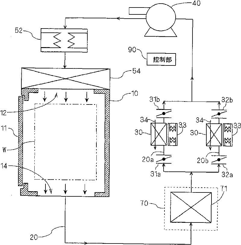
[0035] figure 1 It is a figure which shows the whole structure of 1st Embodiment of the circulation type substrate firing furnace of this invention. This substrate firing furnace fires a rectangular glass substrate W on which color ink, etc. The main body part 10, the circulation path 20 for circulating the hot air, the catalyst filter part 70 carrying the catalyst for decomposing organic matter on the filter, the adsorption tower 30 for adsorbing the moisture and carbon dioxide contained in the hot air, and the circulation Fan 40, main heater 52 for heating hot air, metal filter 54. In addition, a control unit 90 is provided on the substrate firing furnace.

[0036]The furnace main body portion 10 is a housing capable of accommodating the glass substrates W in multiple layers (40 layers in the present embodiment). The inner side of the furnace main body portion 10 is formed as a substantially quadrangular prism-shaped heat treatment space. A plurality of forks (not shown)...

no. 2 approach

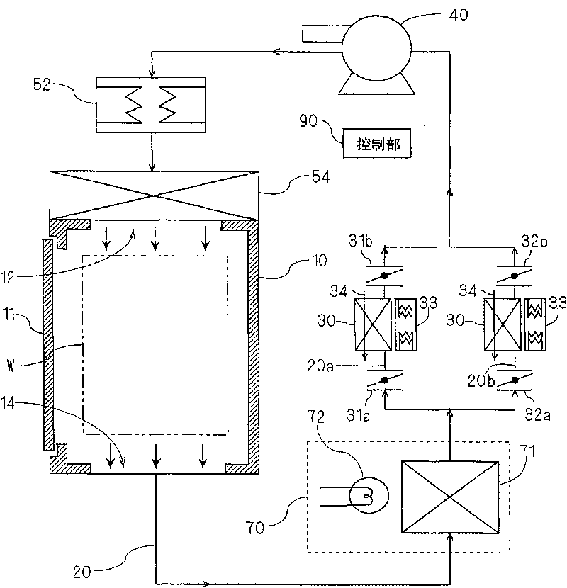
[0059] Next, a second embodiment of the present invention will be described. figure 2 It is a figure which shows the whole structure of the circulation type substrate firing furnace of 2nd Embodiment. exist figure 2 In , the same reference numerals are assigned to the same elements as those in the first embodiment. The difference between the substrate firing furnace of the second embodiment and the first embodiment is that the catalyst filter unit 70 has a light source 72 in addition to the catalyst filter 71 .

[0060] In the second embodiment, part of the catalyst carried on the catalyst filter 71 is mixed with titanium oxide (TiO 2 ). A light source 72 included in the catalyst filter unit 70 irradiates light to the catalyst filter 71 . The photocatalyst carried on the catalyst filter 71 acts as a catalyst by receiving light from the light source 72 . Other configurations of the substrate firing furnace of the second embodiment are the same as those of the first embod...

no. 3 approach

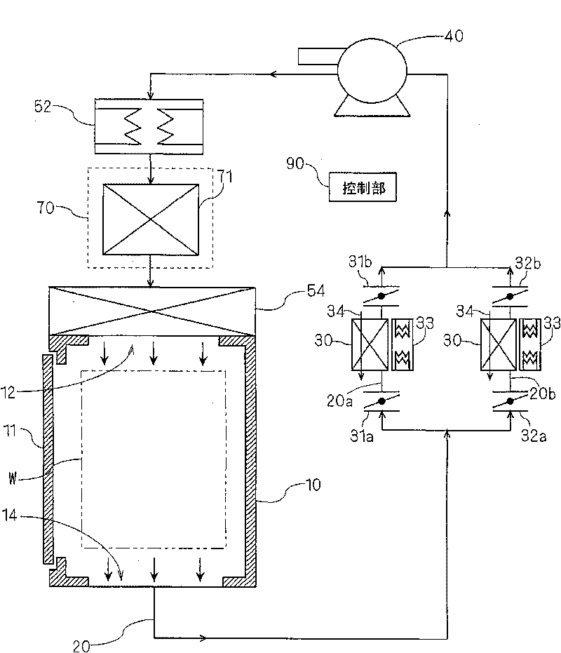
[0063] Next, a third embodiment of the present invention will be described. image 3 It is a figure which shows the whole structure of the circulation type substrate firing furnace of 3rd Embodiment. exist image 3 In , the same reference numerals are assigned to the same elements as those in the first embodiment. The circulation type substrate firing furnace of the third embodiment differs from the first embodiment in the arrangement position of the catalyst filtering unit 70 .

[0064] Such as image 3 As shown, in the third embodiment, a catalyst filter part 70 is provided, and the catalyst filter part 70 is provided on the downstream side of the main heater 52 in the circulation path 20 and is located between the main heater 52 and the furnace main body part 10. between. Other configurations of the substrate firing furnace of the second embodiment are the same as those of the first embodiment.

[0065] In the third embodiment, the hot air discharged from the hot air o...


PUM


Abstract

The invention provides a circle substrate firing furnace which can reduce the heat loss and obtain the steady sintering temperature. The sintering treatment of a glass substrate (W) can be performed by blowing out the hot blast from a furnace main body part (10). the hot blast exhausted from the furnace main body part (10) cycles in a circulating path (20) by a circulating fan (40), passes through an adsorption tower (30) for adsorbing and decomposing the resultant from a catalyst filtering part (70) for decomposing the organic compounds, and is heated again in a main heater (52). The hot blast exhausted from the furnace main body part (10) directly flows into the catalyst filtering part (70), thereby the organic compounds contained in the hot blast can be decomposed, thus no additional single heater is needed for heating the catalyst, the heat loss can be reduced. In addition, the sintering temperature in the furnace main body part (10) can be adjusted by controlling the main heater (52), therefore the temperature can be easily controlled to obtain the steady sintering temperature.

Description

technical field [0001] The present invention relates to a circulation type substrate firing furnace which heats a glass substrate for a liquid crystal display device, a glass substrate for a PDP (plasma display panel), and a semiconductor wafer while circulating hot air. Substrates for thin plate-shaped electronic components (hereinafter referred to simply as "substrates") are subjected to firing treatment. Background technique [0002] As one of the manufacturing steps of a color filter, there is a step of firing a glass substrate to which a color ink is adhered by inkjet. This firing step is performed by holding the glass substrate in an air atmosphere for a predetermined time in a firing furnace heated up to a predetermined firing temperature. In addition, when forming metal wiring on a glass substrate, the glass substrate is fired in an inert gas atmosphere such as nitrogen in the same firing furnace. In all firing processes, since the organic solvent contained in the ...

Claims


Application Information

Patent Timeline
IPC IPC(8): F27B17/00H01L21/00C03C17/00
CPCF27B17/0025H01L21/67017H01L21/67098
Inventor 大见忠弘村冈祐介宫路恭祥
Owner FUTURE VISION
Why Eureka
Try Eureka