Micro-projection optical engine

An optical engine and micro-projection technology, applied in the field of projection display, can solve the problems of inability to meet the requirements of miniaturization, light weight, many optical components, and complex structure, and achieve the effect of simple structure, small size, and high utilization rate of light energy.

Inactive Publication Date: 2010-06-23
BUTTERFLY TECH SHENZHEN
View PDF1 Cites 8 Cited by
  • Summary
  • Abstract
  • Description
  • Claims
  • Application Information

AI Technical Summary

Problems solved by technology

The projector with this structure requires each light-emitting diode assembly to emit light at the same time. At the same time, it needs three panels combined with three polarizing beam splitters, which has low efficiency, and the structure is complex, and the optical components used are many, and the optical path is relatively long. Long and large in size, unable to meet the miniaturization and lightweight needs of the market

Method used


Image

  • Micro-projection optical engine
  • Micro-projection optical engine
  • Micro-projection optical engine

Examples


Embodiment Construction

[0012] The present invention will be further described below in conjunction with the accompanying drawings and specific embodiments.

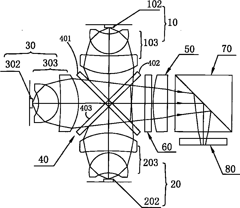
[0013] figure 1 Shown is a schematic plan view of the micro projection optical engine according to the first embodiment of the present invention, which includes a red light source module 10, a blue light source module 20, a green light source module 30, a cross-shaped dichroic mirror 40, and a lens group 50 , a polarization converter 60 , a polarization beam splitter 70 , a single microdisplay panel 80 and a projection lens (not shown in the figure). Among them, the red light source module 10 , the blue light source module 20 , the green light source module 30 , the cross-shaped dichroic mirror 40 , the lens group 50 and the polarization converter 60 constitute an illuminating device.

[0014] The red light source module 10 includes a red semiconductor light emitting element 102 and a first shaping lens group 103 for collecting and shaping the...


PUM


Abstract

A micro-projection optical engine comprises an illumination device, a polarization optical splitter, a monolithic micro-display panel and a protection lens, wherein the illumination device comprises a red light source module, a blue light source module, a green light source module, an X-type color combination lens and a lens group. The lens group is arranged on an output light path of the X-type color combination lens. The polarization optical splitter is arranged on the output light path of the illumination device. The monolithic micro-display panel is arranged at one side, which is not adjacent to the illumination device, of the polarization optical splitter, modulates and converts the received polarized light into another polarized light which is vertical to the polarized light, and makes the other polarized light carry image information. The projection lens receives and projects the other polarized light carrying image information. The invention improves the efficiency of the optical engine by the lens group, meanwhile, the whole optical engine only involves the illumination device, the polarization optical splitter, the monolithic micro-display panel and the projection lens, the invention has simple light path design, compact structure, uniform radiance, small size and lower production cost.

Description

technical field [0001] The invention relates to projection display technology, in particular to a three-primary-color miniature projection optical engine. Background technique [0002] In recent years, liquid crystal projection technology has been widely used in audio-visual teaching, office, business, advertising and entertainment. With the development of science and technology and the improvement of people's living standards, liquid crystal projection technology is also developing in the direction of miniaturization, light weight and high image quality. [0003] The publication number "CN1609703" in the Chinese Invention Patent Application Publication, titled "Light Emitting Diode Lighting Device", discloses a projector using a light emitting diode lighting device, which includes a red light emitting diode component, a green light emitting diode component and a blue light emitting diode component. The light emitting diode component consists of multiple light emitting diod...

Claims


Application Information

Patent Timeline
Patent Type & Authority Applications(China)
IPC IPC(8): G03B21/20G02B27/10G02B27/28
Inventor 曲鲁杰高国欣王仁贵林晶
Owner BUTTERFLY TECH SHENZHEN
Why Eureka
Try Eureka